
Receiver Noise Figure Calculation:
It is defined as the measure of noise produced by a practical receiver compared to noise of an ideal receiver. The noise figure is expressed as,
Fn = Nout/KToBnG
Where, Nout – available output noise power
K – Boltzmann’s constant
G – Gain
To – Standard temperature
Bn – noise bandwidth
If additional noise is introduced by practical network, then
Noise figure = Fn = (KToBnG + ΔN)/ KToBnG
Fn = 1+ ΔN/ KToBnG
Noise Figure in Cascade Networks:
Consider two networks in cascade each with same noise and Bandwidth but with different gain. Let the noise from the first network be F1KT1BnG1G2 and the noise from second network be (F2-1) KToBnG2.
Therefore, the output noise, Nout = noise from first network + noise from second network
ie, Nout = F1KT1BnG1G2 + (F2-1) KToBnG2
Let, Nout = FoKT0BnG1G2
Therefore the above equation becomes,
FoKToBnG1G2 = F1KT1BnG1G2 + (F2-1) KToBnG2
Fo = [F1KT1BnG1G2 + (F2-1) KToBnG2]/ KToBnG1G2
provides two output frequencies that are sum and difference of two input frequencies.
ie, fRF ± fLO
The difference frequency fRF - fLO is the desired IF frequency. The sum frequency fRF + fLO is removed by filtering. The RF Signal frequency is greater than local oscillator frequency, the output IF frequency will be,
fIF = fRF - fLO
This is known as derived frequency.
• If the RF Signal frequency is less than local oscillator frequency, then the output IF signal will be,
fIF = fLO - fRF. This is called Image Frequency.
MIXERS:
a. Single Ended Mixer:

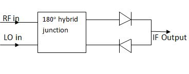
b. Balanced Mixer:
c. Image Rejection Mixer:
