
In general the term, 'Electronic Voltmeter' applies also to electronic test meters. A test meter will have a provision for measuring the basic quantities the ampere, the volt and the ohm. Hence the once very popular analog type of `AVO' multimeter. An electronic test meter is an instrument that is capable of measuring current, voltage and resistance basically. It can also be used to measure power, gain in decibel. It can be used to test the electronic components or devices to reject defective ones.
The heart of any electronic test meter is an electronic voltmeter. We measure the voltage only from which we estimate automatically the quantities like current, power, resistance etc.
In a nut shell, electronic voltmeter measures only voltage. Electronic test meter can be used to measure voltage, current, resistance etc. The term multimeter is commonly used to refer a test meter. At present we are calling electronic multimeters as digital multimeters as most of them (all of them) have a digital readout and use a basic system of a digital milli voltmeter module.
Depending on the devices used in the test meter they are of two types :
(a) Vacuum tube type.
(b) Transistorized (Semi-conductor type) and
(c) Using integrated Circuits
Depending on the type of display they are again of two types
(a) Analog (analogue) type.
(b) Digital type.
According to their principle of operation they are of two types:
(a) The amplifier rectifier type.
(b) The rectifier amplifier type.
The amplified signal is rectified. The rectified DC is used in a difference amplifier. The indicating instrument in the difference amplifier indicates a current which is proportional to the input. The meter is calibrated in terms of R.M.S volts. Alternately a digital circuit can be made to work from the output of the rectifier. The output will be displayed in this case by a digital display.
The rectifier amplifier type is preferred when signals of high frequency are to be measured. One feature of these instruments is that the probe itself can be made to have the rectifier unit. Hence no signal at signal frequency will be coupled to the instrument through the probe. The sensitivity of these voltmeters is not as good as that of the amplifier rectifier type of voltmeters. They have good frequency range of the order of 100 Hz to 500 MHz. The sensitivity will be of the order of 0.5 V (peak) full scale deflection
The heart of any electronic test meter is an electronic voltmeter. We measure the voltage only from which we estimate automatically the quantities like current, power, resistance etc.
In a nut shell, electronic voltmeter measures only voltage. Electronic test meter can be used to measure voltage, current, resistance etc. The term multimeter is commonly used to refer a test meter. At present we are calling electronic multimeters as digital multimeters as most of them (all of them) have a digital readout and use a basic system of a digital milli voltmeter module.
TYPES OF ELECTRONIC TEST METERS :
Depending on the devices used in the test meter they are of two types :
(a) Vacuum tube type.
(b) Transistorized (Semi-conductor type) and
(c) Using integrated Circuits
Depending on the type of display they are again of two types
(a) Analog (analogue) type.
(b) Digital type.
According to their principle of operation they are of two types:
(a) The amplifier rectifier type.
(b) The rectifier amplifier type.
AMPLIFIER RECTIFIER AND RECTIFIER AMPLIFIER TYPES:
(a) The Amplifier Rectifier Type
In this instrument, the signal under measurement will be first amplified. This amplification will be done in a wide band amplifier. The block diagram is shown in Figure. |
| Block Diagram of Amplifier Rectifier Type of Voltmeter |
The amplified signal is rectified. The rectified DC is used in a difference amplifier. The indicating instrument in the difference amplifier indicates a current which is proportional to the input. The meter is calibrated in terms of R.M.S volts. Alternately a digital circuit can be made to work from the output of the rectifier. The output will be displayed in this case by a digital display.
(b) The Rectifier Amplifier Type
In this type of instrument the signal is first rectified. The rectified D.C. will be amplified. The amplified signal will be applied either to an indicating instrument or to a digital circuit that produces the display. The block diagram is shown in Figure.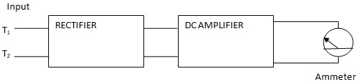 |
| Block Diagram of the Rectifier Amplifier Type of Voltmeter |
(c) Applications of Amplifier Rectifier and Rectifier Amplifier Type
Amplifier rectifier types are used at audio frequencies. They are useful in measuring voltages of smaller amplitudes. They cannot be used beyond 10 MHz. The reason is that at high frequencies, the probe offers considerable inductance and stray capacitance. This leads to erroneous results.The rectifier amplifier type is preferred when signals of high frequency are to be measured. One feature of these instruments is that the probe itself can be made to have the rectifier unit. Hence no signal at signal frequency will be coupled to the instrument through the probe. The sensitivity of these voltmeters is not as good as that of the amplifier rectifier type of voltmeters. They have good frequency range of the order of 100 Hz to 500 MHz. The sensitivity will be of the order of 0.5 V (peak) full scale deflection
Tags:
Multimeters