
A multi-meter is one piece unit combining the ammeter, voltmeter and the ohm-meter. It also provides facilities for the measurement of output power, testing of semiconducting devices, testing and measurement of component values.
From the knowledge of measurement of current, voltage, resistance and power it is clear that in all these measurements the basic instrument used is a moving coil ammeter. So a moving coil ammeter of proper sensitivity can be used with switching facilities, to measure current, voltage and resistance. Additional switching facility will make the instrument useful for measuring the alternating voltage and current. When designed with the above facilities, this instrument also will be useful for miscellaneous measurements listed above. There are several models manufactured with features different from one another. However the basic principle is the same and the basic measuring ranges are common in all the commercially available multi-meters. Before studying the circuit and operation of the multi-meter it is necessary to know the specifications in general of a multi-meter. The specifications are given below.
(a) General Specifications of a Multi-meter :
Multi-meter with sensitivity of 20 kΩ/V on DC and 5 kΩ/V to 8 kΩ/V on AC with the following ranges, having different scales for measurement of alternating current, alternating voltage, direct current and voltage, resistance and dB; having smooth rotary switching arrangement for selection of different ranges, with complete test probes and accessories. The scale is to be provided with a mirror. The multi-meter must have an overload protection.
RANGES REQUIRED
Quantity Measured | Ranges Required | Allowance | Remarks |
DC volts | 0.5 V, 3 V, 12 V, 30 V, 120 V, 300 V, 1200 V battery 1.5 V check 0 — 1.5 V optional. | ±3% fs | Sensitivity 20 kΩ/V |
AC volts | 0.6 V, 30 V, 120 V, 300 V, 1200 V. | ±4% fs | 5 kΩ/Vto 8 kΩ/V |
DC and AC current | 0.100 A, 1 mA, 10 mA, 100 mA, 1 A and 10 A. | ±3% fs | Sensitivity 1 A in 100 A range. |
Resistance | Range; X 1; X10; X1 k; X10 k Min. 0.2 2 Ω 200 Ω 2 k (Ω) Mid. 20 200 20 k 200 k (Ω) Mac. 2 k 20 k 2 M 20 M (Ω) | ±3% of arc | with internal batteries |
dB AF Power | — 10 dB to + 17 dB in one range. 0 dB/0.775 V (1 m W through 600 ohm) — 10 dB to + 6.3 dB on all ranges. | ±4% fs | 8 KΩ/V may be on special socket. |
The above are the specifications of a general purpose multimeter. When a better standard is required the following technical specifications listed may be quoted in addition to the above specifications.
Meter system :
Tautband suspension / Jewel bearing suspension (the former is superior to the latter). Centre magnet. Scale can be mirror scale. Here better specification than one given above is to indicate the current say 25 μA mirror scale. This specification gives a better sensitivity than one specified above.
Calibration: In horizontal position
Reference temperature : 23° C ± 2°
Temperature coefficient : 0.3%°C for say 100 mV D.C range and 0.1 x class accuracy over a range from 13°C to 35°C for other ranges.
Operating temperature: - 10° C to + 55°C
Storage temperature: 40°C to + 70°C
Relative humidity: 10 to 90%
Calibration interval: 1 year
Batteries: as per design requirement (2 x 1.5 volts are preferred in some circuits and 2 x 9 V are used in some others)
Dimensions: Width x depth x height (as per manufacture)
Accessories provided: Voltage multiplier probe. Current transformer or any other requirement.
Frequency Response: The requirement can be as good as 40 Hz to 5 kHz. However the accuracy seldom exceeds 5%. When response is limited to 1 kHz, accuracy of 2.5 % is obtainable.
Many manufacturers supply multi-meters with the above technical specifications, the price of the instrument increases for better specifications. For use in general service work the specifications mentioned under general specifications will be sufficient.
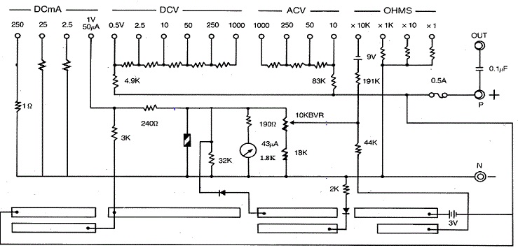
(b) The Schematic Diagram of a Multi-meter :
The schematic diagram of a multi-meter is shown below. In addition to the generally available facilities this instrument can be used as a transistor tester also.
 |
| Schematic Diagram of a Multimeter |
(c) Working of the Multimeter:
The multimeter shown in Figure, above uses one rotary switch to connect the different shunt and series resistances to the basic meter. The other D.P.D.T. switch is the one meant for polarity changing. This switch interchanges the polarity of the basic movement of the multi-meter. This multi-meter can read current from 60 μA full scale deflection up to 12 A in four positions of the rotary switch. The 60 μA setting is the same as 0.3 V (300 mV) position of the rotary switch. 12 A terminal is given separately.
The moving coil meter employed is having internal resistance of 1.5 kΩ. The full scale deflection current is 44 μA. The meter movement is protected by virtue of the automatic protection circuit using Silicon diodes placed in parallel with the meter movement. Pulse current flowing into the movement is absorbed by them to safeguard the moving coil from damage.
The shunts required for the D.C. range are brought into the circuit by the rotary switch, in the appropriate positions.
The D.C. voltage can be measured from 300 m V to 1200 V in six positions of the rotary switch, which connects the multiplier resistances of appropriate value in series with the meter circuit. The 300 m V is common with 60 μA position of the current measurement.
Alternating voltage from 6 V to 1200 V can be measured in five steps of the rotary switch that brings the multipliers and the rectifying diodes into the circuit. It can be seen from the values of multiplier resistances of the circuit that their values are lower than for the D.C. voltage range.
Resistance can be measured with a mid-scale reading of 20 Ω, 200 Ω, 20 kΩ, and 200 kΩ; in the multiplying positions by 1, 10, 1 k, and 10 k. There are two internal batteries used giving 3 V, for X1, X10, 1 k, multiplication ranges. The X10 k multiplication is obtained with a 12 V battery. 3 V supply is obtained by 2 x 1.5 V cells, 12 V supply is obtained by connecting in series to 3 V, a 9 V battery. The individual limiting resistors and battery are brought into the circuit by the rotary switch in those positions respectively.
A separate terminal marked as output terminal is used for measurement of audio power expressed in dB. A capacitor is connected in series with this terminal. It prevents any D.C. from appearing in this circuit. To measure A.F. power the rotary switch is to be brought to A.C 6 V. to read in -10 dB to +17 dB scale. Any range can be used with the addition of dB as per the table given over the dial plate of the instrument.
Transistors, diodes including LEDs can be tested using the resistance ranges. Leakage current can be read out from the scale markings. The hfe of the transistor can also be measured with the connector provided as accessory.
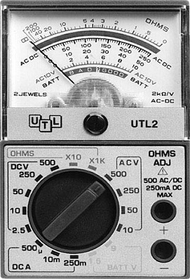 |
| Front Panel of Multimeter |
A figure showing the front panel of a multi-meter is shown above.
Tags:
Multimeters