
MICROPHONES:
We can define a microphone as "an electro-acoustic transducer that transforms sound waves into varying electrical currents". There are two types of microphones. They are namely:
i) Pressure Microphone and
ii) Pressure Gradient Microphone
i) Pressure Microphone
In pressure microphones, acoustic pressure operates on just one side of the moving element in pressure microphones, and the output is proportionate to the pressure applied to the moving element.
Examples of pressure microphones are:
1. Carbon Microphone
2. Condenser Microphone
3. Piezo - Electric Microphone and
4. Moving Coil Microphone
ii) Pressure Gradient Microphone
The acoustic pressure acts on two sides of the moving element in pressure gradient microphones, and the resultant output is proportional to the difference in pressure acting on the two sides of the moving element. Example: Velocity Ribbon Microphone.
A. CARBON MICROPHONE:
A carbon microphone is a small container packed with carbon grains known as a carbon button. The button is in continuous contact with a thin steel diaphragm through an electrode known as the plunger. When no sound waves contact the diaphragm, the resistance of the carbon button stays constant. When sound waves contact the diaphragm, it displaces and the plunger linked to it changes the pressure exerted to the carbon button. As a result, the resistance of the carbon button varies.
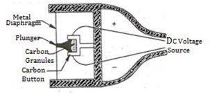
Figure 1 Simple Carbon Microphone
The figure illustrates a carbon microphone diagram. The carbon button is connected to a dc power source. A dc voltage source is linked in series with the carbon button. As a result, the sound waves change the circuit current in response to changes in resistance.
Applications:
1. It's prevalent in telephones.
2. It can be effectively employed in radio communications.
Advantages are:
1. Electrical output is high.
2. Cost-effective.
3. It is sturdy (strong).
Disadvantages:
1. Low-frequency response
2. Lack of faithfulness.
3. It makes a lot of noise when it operates.
B. CONDENSER OR CAPACITOR MICROPHONE:
A condenser microphone relies on capacitance, which changes between a fixed plate and a tightly stretched metal diaphragm to operate. It is made up of two extremely thin plates, one of which is moveable and the other one is fixed. A capacitor is made up of these two plates. Since it was originally known as a condenser, it is now known as a condenser microphone. The diaphragm, or moving plate, is separated from the fixed plate by a short distance.

Figure 2 Condenser Microphone
Between the plates, a polarising voltage (Eo) is applied. The figure shows a condenser microphone. When a sound wave impacts the diaphragm, it displaces the diaphragm and alters the distance between the two plates, which affects the capacitance of the microphone.
Applications:
1. Used as the principal standard in calibration.
2. Used to record high-quality sound.
Advantages are:
1. Extensive frequency response
2. Minimal distortion
3. Extremely compact.
4. Good signal-to-noise ratio (S/N).
Disadvantages:
1. Because of its high internal impedance, it necessitates the use of a built-in pre-amplifier.
2. A polarising voltage of 200 to 400 volts is required.
3. Produces a small Output.
C. PIEZO-ELECTRIC MICROPHONE (OR) CRYSTAL MICROPHONE:
A crystal microphone operates based on the ‘Piezoelectric Effect,' which is described as the ‘difference in potential between the opposite sides of particular crystals created when they are exposed to mechanical pressure.' A crystal microphone is made up of a Bimorph, which is just two crystals linked in series or parallel. If the crystals are linked in series, the output result is in the form of voltage. The parallel connection has a lower internal impedance. A driving pin connects one end of the bimorph to the diaphragm's center. The figure shows the schematic diagram of this microphone.

Figure 3 Diaphragm Actuated Crystal Microphone
When sound waves get in touch with the diaphragm, variable pressure is delivered to the crystal through the connecting pin, and changing voltage is created between the plates.
Applications:
1. In a public address system.
2. Found in hearing aids.
3. Found in sound level meters.
Advantages:
1. High sensitivity.
2. The frequency response is good.
3. Low cost.
4. Small size.
5. It is a non-directional microphone.
6. Produces a lot of production.
7. A polarised source is not required.
Disadvantages:
1. Influenced by temperature and humidity.
2. High mechanical impedance of its vibrating components.
3. Not appropriate for hot regions since the crystal loses its piezoelectric characteristics.
D. MOVING COIL (OR) ELECTRODYNAMIC MICROPHONE
A moving coil microphone is made out of a tiny wire coil that is held in high magnetic fields and rigidly connected to the back of the diaphragm. The diaphragm is corrugated to increase its strength and mobility. The figure depicts a moving coil or electrodynamic microphone.
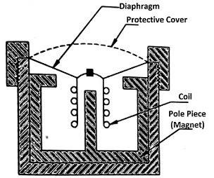
When sound waves hit the diaphragm, it travels back and forth, dragging the coil along with it. The coil's motion cuts the magnetic lines of force and produces an alternating current voltage in the coil. The frequency of the alternating current voltage is the same as the frequency of sound waves. The amplitude of this voltage is proportional to the air pressure of the sound waves.
Application:
1. Used for recording systems both indoors and outdoors.
Advantages:
1. There is a low internal impedance.
2. Constant frequency response
3. It does not require any external power.
4. It is lightweight.
5. Unaffected by mechanical vibration, temperature, or moisture.
Disadvantages
are:
1. The open-circuit voltage sensitivity is low.
E. VELOCITY RIBBON OR PRESSURE GRADIENT MICROPHONE:
The velocity ribbon microphone operates on the pressure gradient principle, which states that the driving force exerted on a moving element is proportionate to the difference in pressures acting on its two sides. The figure depicts a velocity ribbon microphone.

Figure: Velocity Ribbon Microphone
It is made up of a light corrugated metallic ribbon hung between the magnetic pole components n and s, which is open to sonic stresses on both sides. The resulting driving power is proportional to the pressure differential between the diaphragm's two sides (Ribbon). This construction is installed in a circular baffle with radius l, which defines the length of the air route between the two sides of the ribbon. When a sound wave strikes the ribbon, it travels back and forth in proportion to the sound's velocity. It causes a voltage to be generated in the ribbon by cutting the force lines between the magnet's poles. This voltage is relatively low, however, it may be raised with a transformer.
The word ‘directivity' in a microphone refers to how much signal it receives from each direction, ranging from 0 to 3600. The bi-directional feature of a velocity ribbon microphone is depicted in the Figure below. The bi-directional microphone receives the strongest signal between 00 and 1800 and no signal between 900 and 2700.

Figure: Bi-Directional Characteristics of Velocity Ribbon Microphone
1. Applicable for studio works.
Advantages:
1. Better frequency response than moving coil type.
Disadvantages:
1. It requires a built-in transformer due to its low internal impedance.