
UNIVERSAL COUNTER:
Universal Counter can be defined as: A counter counts the number of cycles over a second. With the advent digital integrated circuits the design of electronic counters has become easy. An electronic counter can be used to count or measure frequency, time period, time interval between two actions and to determine the ratio between two frequencies. It can be used as count totalizer. The advantage of a digital counter is that it displays its count, frequency or time period etc., on a numeric display, offering all the advantages of digital displays.
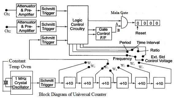
A universal Counter is a one piece combined unit that has in it all the circuits for measurement of frequency, time period, frequency ratio etc. Desired functions can be selected using the function switch. Block diagram of the universal counter is shown in Figure.
BLOCK DIAGRAM OF UNIVERSAL COUNTER:
There are two channels for the input named as chl and ch2. The input signal reaches the preamplifiers through the attenuators. Two Schmitt trigger circuits are fed from the output of the two preamplifiers. The two Schmitt triggers present their outputs to the Logic Control Circuitry. The second channel is meant for frequency ratio and multiple ratio measurement.
The block Logic Control Circuitry contains logic gates that are enabled or disabled depending on the selection of the function by the function switch and on the status of the inputs to the L.C.C. The output from the Logic Control Circuitry directly reaches one input of the Main Gate. The Main Gate output drives a decimal counter. The output of the decimal counter drives a decoder driver which drives the display unit.
The second input to the Main Gate is derived from Gate Control Flip Flop. The gate control flip-flop is controlled by the output of the logic control circuit.
The crystal oscillator (also called the clock oscillator) generates an output voltage at 1 MHz, and is sinusoidal in its nature. The crystal oscillator offers excellent frequency stability. In order to improve on the long term frequency stability, the crystal oscillator is kept in a constant temperature oven.
The output of the crystal oscillator is given to a Schmitt trigger circuit. This converts the sinusoidal voltage of the crystal oscillator in to train of pulses. The rate of the pulse train offered by the Schmitt trigger will be equal to the frequency of the clock oscillator.
The output from the Schmitt trigger is presented to a chain of decade dividers. The output of the Schmitt trigger, as well as the outputs of the decade dividers is brought over the ways of a selector switch. The selector switch has seven ways w1 to w7, and we can select pulses from 1 μs to 1 s. These are the time base pulses to the logic control circuitry, again through another Schmitt trigger.
Tags:
Power Supplies