
The block diagram showing a digital voltmeter of successive approximation type is shown in Figure.
(a) Description of the Block Diagram:
It consists of input attenuator and amplifier. The output of the input amplifier is given to the sample and hold circuit. There is a reference supply source whose output is given to the D/A converter. The output from the sample and hold circuit and D/A converter is given to a comparator. The output from the start stop multi is given to the delay circuit. The delay circuit's output goes to the gate. The gate is connected to the control register. The ring counter gives its output to the control register, and also to the start stop multi. The control register's output goes to the digital readout circuitry.
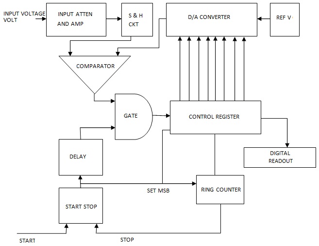 |
| Block Diagram of Successive Approximation Type DVM |
(b) Working:
We start from the start stop multi. To commence measurement cycle a start pulse will be applied to the start stop multi. This results in setting up of ‘1' in the most significant hit of the control register. A '0' is set at all bits of less significance. Let us assume that the control register is an 8 bit register.
With this setting its reading will be 1000 0000. For this initial setting of the control register the D/A converter produces an output of one half (1/2 E) of the reference supply voltage. As can be seen from the block diagram the D/A converters output is given to the comparator. The comparator also has its input from the input side of the sample and hold circuit. If the input voltage is more than the reference voltage produced by the D/A converter, the comparator gives an output, retaining the contra` register to stay in the initial setting of 1 in the most significant bit. The D/A converter goes on supplying the half reference voltage.
Now the ring counter advances the count by 1 in the second MSB of the control register. Its reading therefore becomes 1100 0000. This makes the D/A converter to enhance its output by another half i.e. half plus one fourth i.e. 3/4 E. Again the comparator compares the reference voltage with the input voltage. If in this comparison the reference voltage is more than the input voltage the comparators output changes. This change causes control register to reset the second most significant bit to '0’. This makes the D/A converter to return to the previous level of 1/2 E Volts. The DA converter now awaits another input from the control register for the next approximation. The ring counter in its turn advances by another count. Now the third most significant bit of control register will be set to 1. The D/A converter produces an output of half plus one eighth of the reference voltage.
This way the measurement cycle continues over a series of successive approximations. During this course the converters output is either retained or rejected as explained above. The series of successive approximations are shown in Figure. Ultimately the ring counter reaches the last count. The measurement cycle stops. The digital output of the control register now gives the Final approximation of unknown voltage.
 |
| Successive Approximation Type DVM |
The sample and hold circuit in the input of the DVM is to prevent the conversion error. This is because of the fact that when voltages other than D.C. are measured, conversion results are inconsistent. The simplest form of sample and hold circuit consists of a switch and a capacitor.
When the switch is closed the capacitor gets charged to the instantaneous value of the applied voltage. This is termed the sample mode. If the switch is open the capacitor retains the charge it acquired during the instant of charging.
The switching is made synchronous with the ring counter pulse. The measurement and conversion occurs when the switch is open, which is called the hold mode. Practically electronic switching is used.
Tags:
Multimeters