
The digital panel meter is one that can be used to measure voltage or current, or power as desired by us by proper design of the instrument. The present day trend is to use these digital panel meters in laboratories and in electronic instruments. They give added attraction to the instruments and give a look in laboratories. They give an attractive front panel when they are used in test instruments.
As mentioned above a digital panel meter is nothing but a digital voltmeter with an attractive type of L.E.D. display of the desired colour. The required adaptor for measurement of alternating voltage, current , either D.C. or A.C., or power or any other quantity can be added to this module.
To be frank the digital hand meter and the digital multimeter literally mean the same. Then why the two specific objectives? It is assumed that the digital hand meter is the digital panel meter.
A digital panel meter or a digital multimeter will use a CMOS LSI. The I.C. has high performance and low power consumption. It is a three and half digit A/D converter. Intersil 7107 single chip A/D converter has in it the active devices, seven segment decoders, display driver, reference and a clock. This can drive instrument size LED displays directly. Another IC the 7106, offers the same facility but will drive LCD. The two I.C.s are basically d.c.voltmeters. Proper selection of components will make the I.C. to work either as a 200 µV full scale reading voltmeters or a 2 V, F.S.D. voltmeter. Normally the 200 mV mode is preferred. This single chip A/D converter works on dual slope conversion principle.
(a) Block Diagram of a Digital Panel Meter :
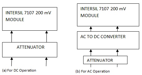
The block diagram is shown in Figure.
Description: To make it as a panel meter for measurement of steady voltage (D.C. voltage ) we require a proper attenuator. The attenuator can contain different resistances arranged as potential divider. The resistance values are selected according to the multiplication factor of the range from lowest range of 200 mV. With proper arrangement it can be used for panel mounting to indicate required voltage.
To make a panel meter that can measure steady voltage (D.C. voltage) we require only the attenuator and range selector switch. So these two are to be shown as additional blocks in the diagram shown under Figure.
If it has to measure alternating voltage we require rectification of the voltage. Using an operational amplifier and diodes this can be done. So the additional block to the diagram of Figure, to act as a panel meter to measure alternating voltage is A.C to D.C. converter.
 |
| Digital Panel Meter Block Diagram |
The block diagrams for measuring steady voltage, and alternating voltage are shown above : The 200 mV module is shown only as a single block. The block diagram of 7107 and that of the panel meter are given above to present a clear picture of panel meter, which uses the D.V.M module.
Tags:
Multimeters