
(a) Rectifier Amplifier and Amplifier Rectifier Type Electronic Voltmeters:
The rectification can be done before D.C. amplification. It can also be done after amplifying the signal. These two are the known rectifier amplifier and amplifier rectifier versions. Either of the types can be used with the above circuits. The important consideration is the rectification.
(b) Types of Rectifiers Used :
The rectifiers used arc of the following types:
(i) Series connected diode (Half wave rectification) giving average reading.
(ii) Bridge connection of diodes (full wave Bridge rectifier) giving average reading.
(iii) Parallel connected diode, giving peak reading.
If the half wave or full wave circuits are used, the reading is to be multiplied by form factor. Form factor for sinusoidal waves is 1.11. The reason is that all meters measuring alternating voltage to be calibrated in terms of R.M.S. volts only. As the rectifier output will be only the average value, the indicating meter indicates the average value of voltage. Hence the scale of these type of rectifier type of electronic voltmeters will be calibrated in R.M.S. volts.
(c) Measurement of Current Using Electronic Voltmeter :
Direct current can be measured using Electronic Voltmeter using a standard resistance. This standard resistance will be incorporated in the instrument itself. A function switch brings this standard resistance in to circuit. The unknown current will be allowed to circulate through the standard resistance. The voltage drop across the standard resistance will be given to the balanced D.C. amplifier. As the voltage drop across the resistance is proportional to the current flowing through the resistance. The voltage shown by the balanced D.C. amplifier can be calibrated in terms of current.
Alternating current also can be measured in the same way with the only change that the alternating current will be rectified before it is passed through the standard resistance. The function switch does the job of sending the rectified current proportional to the input alternating current through the standard resistance. The voltage across the standard resistance is measured.
The alternating voltage as is calibrated in R.M.S. value, the R.M.S. current can he measured by calibrating the voltage readings in terms of current.
(d) Measurement of Resistance Using Electronic Voltmeter:
Measurement of resistance using electronic volt meters is very simple. All quantities are measured in terms of the voltage only, in the electronic voltmeters. Therefore the resistance measurement also uses a way of measuring proportional voltage corresponding to the value of the unknown resistance. An arrangement is shown in Figure.
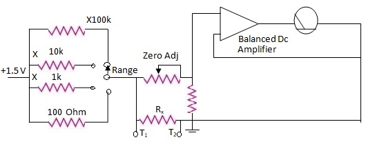 |
| Arrangement for Measurement of Resistance in Electronic Voltmeters |
This is also an indirect method of measuring resistance. A voltage source, and number of standard resistances for range selection are used. The unknown resistance will be connected in series with the standard resistance to form a potential divider with the voltage source. The voltage dropped across the unknown resistance will be measured.
In the above Figure we have four resistances connected to the 1.5 V cell. The other ends of the resistances are brought over to the ways of the range selector switch. The ohms terminals are shown as common and in the circuit. It is across these terminals the unknown resistance will be connected. A function switch may be used to bring the external resistance in series with the voltage source and series resistance combination. This is done in some models. Otherwise the resistance / Ω terminals are separately provided.
Let us assume that in the first setting of range selector we have a standard resistance of 100 Ω. When the test terminals are open, the entire 1.5 V reaches the balanced d.c. amplifier. The arrangement is such that the balanced D.C. amplifier indicates in its output a full scale deflection in the meter. Now it is clear that when the test terminals are open the indication is full scale deflection. That is the meters deflection indicates infinite resistance. Now let us short the test terminals for resistance. The input to the balanced D.C. amplifier is zero. Hence it indicates zero volts. It is clear that for zero resistance the indication is zero. So the balanced D.C. amplifier's indicating meter can be calibrated in terms of resistance. A zero voltage is zero resistance. The full scale reading of volts is equal to infinite resistance.
When intermediate values of resistance are connected as unknown values, the voltage drop across the unknown resistance is applied to the balanced D.C. amplifier. As the voltage developed across the unknown resistance is proportional to the resistance value, by using standard values of external resistance the dial can be calibrated in terms of resistance.
In the first position of the range selector switch we assumed the standard resistance to be 100 Ω. Therefore when an external resistance of 100 Ω is connected the voltage drop will be half of the applied voltage, i.e. 0.75 V. As the design is to obtain full scale deflection for 1.5 V at the input of the balanced D.C. amplifier, 0.75 V gives half scale deflection.
Therefore the half scale deflection of the meter indicates the internal standard resistance. Several ranges can be had by providing several resistances. In the above circuit four ranges are possible. They can be Ω, x 1 k, x 10 k, x 100 k. The preset in the input of the balance D.C amplifier is for zero adjustment in ohms. That is it can be used to ensure correct zero when the ohms test terminals are shorted.
(e) Conventional ohm Meter and Electronic ohm Meter a Comparison :
It is important to note that the electronic ohm meter gives forward reading. In conventional ohm meters we get backward reading of resistance. The reason is that the electronic ohm meter indicates the resistance proportional to the voltage drop across the standard resistance. As the voltage drop increases with the increase in resistance, forward reading is obtained. In conventional ohm meters, we read the current in proportion to the resistance value. As the current decreases with resistance, reverse reading or backward reading is obtained. Further it is to be known that the backward reading of ohms is obtained only in the series type of ohm meter. However the forward reading of resistance can be obtained in conventional ohm meter of the shunt type.
Tags:
Multimeters