
Klystron in Microwave Engineering
A Klystron is a velocity modulated tube, in which the velocity modulation process produces a density modulated stream of electrons. Figure shows the '2-cavity klystron amplifier'. It is distinguished that a high velocity electron beam is created. It is a high positive potential with respect to cathode. Magnetic focusing is used here.
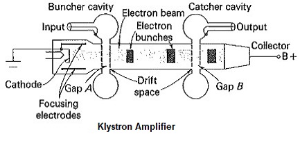 |
| Klystron Amplifier |
A 2-cavity klystron amplifier comprises of a cathode focusing, electrodes, two buncher grids divided by a extremely small space appearing a gap A, two catcher network with a small gap B trail by a collector. The input and output are taken from the tube via resonant cavities. The separation between buncher grids and catcher grids is called, 'drift space'. The electron beam passes gap A in the buncher cavity to which RF signal to be amplified is applied and is then allowed to drift freely without any interference from RF fields until it reaches the gap B in the output or catcher cavity.
The first grid controls the number of electrons in the electron beam and serves to focus the beam. The velocity of electron in the beam is determined by the beam accelerating potential. On leaving the region of first grid the electrons pass through the grids of buncher cavity. The grids of the cavity allow the electrons to pass through, but confine the magnetic fields within the cavity. The space between the grids is called 'inter-action space'. When electrons travel through this space, they are subjected to RF potentials at a frequency determined by the cavity reasonably frequency or the input frequency. The amplitude of this RF potential between the grids is determined by the amplitude of the incoming signal in case of the amplifier, or by the amplitude of the feedback signal from the second cavity if used as in oscillator. Then oscillations will be excited in the second cavity which is of a power much higher than in the buncher cavity, so that a large output can be taken.
Applications:
A multicavity klystron can be used as a medium or high power amplifier in the UHF and microwave ranges, for both continuous and pulsed operations. The power ranges vary from 10kW to 25MW. The power gain ranges from 30dB to 60dB.