
Lumped Parameter Delay Line in CRO:
The lumped parameter delay line consists of symmetrical L.C. networks connected in cascade. When such a section (T section for example) is terminated in its characteristic impedance, the looking back impedance will also be the characteristic impedance. This section now behaves as a low pass filter whose attenuation and phase shift are functions of frequency.
The pass band of such a filter is defined as the frequency range over which the attenuation is zero. The cutoff frequency is 1/ π√(LC).
If we pass signals through such a section whose frequencies are far lower than the cut off frequency of the section, the output will be faithful reproduction of the input. The important point here is that though the output is a faithful reproduction of the input, the output appears only after a delay. This is what exactly we want from a delay line. The delay time is given by :
td = 1/fcπ = √(LC) approximately.
When number of such sections are cascaded in to a lumped parameter delay line. The total delay time will be multiplied by 'n' where n is the number of T sections in the delay line. Hence Td = n.td, where 'n' is the number of cascaded T sections.
The lumped parameter delay line suffers from phase distortion at high frequencies of the input signal. The response of the delay line for step input has over shoot and ringing which is called the transient response distortion. Use of 'm' derived filters improves the system. In any case the impedance matching is very important. The sections must be terminated in the characteristic impedance, that requires complex termination circuitory. A practical push pull driven delay line is shown in the following Figure.
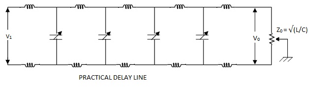 |
| PRACTICAL DELAY LINE |
Distributed Parameter Delay Line :
A specially manufactured coaxial cable with large value of inductance per unit length makes a delay line of this type. The straight centre conductor is replaced by a continuous coil of wire, wound on a flexible inner core in the form of a helix. Eddy currents are minimised by the use of braided insulated wire, electrically connected at the ends of the cable. The construction of such a delay line is shown explained below.
The inductance of the delay line is offered by the inner coil. The inductance can be increased by winding the helical coil over a ferromagnetic core. This increases the delay time and also the characteristic impedance. The capacitance of the delay line is that of the two coaxial cylinders separated by a polyethylene dielectric. Using a thinner dielectric the capacitance can be increased. The parameters of a helical high impedance delay line are typically 1000 Ω of Z0. and 180 ns/m delay time td.
The coaxial delay line is advantageous compared to the lumped parameter delay line in that, it requires a smaller space and does not require critical adjustments.
Tags:
Cathode Ray Oscilloscope