
The Maxwell Bridge is shown in the figure below. It measures an unknown inductance in terms of a known capacitance. The unknown inductance with its resistance is represented as LX and RX respectively. The parallel combination of the variable resistance R1 and the capacitor C1 forms a ratio arm. A variable resistance R3 and resistance R2 take the positions of the two other arms of the bridges.
The balance condition is obtained as shown below:
The Maxwell Bridge Advantages and Disadvantages are as follows.
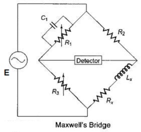 |
| Maxwell Bridge Circuit Diagram |
Taking Zx = Z2Z3Y1
Z2 = R2
Z3 = R3
Y1 = 1/R1 + jωC1
Therefore Zx = Rx + jωLx = R2R3 (Y1)
= Rx + jωLx = R2R3 (1/R1 – jωC1)
= Rx + jωLx = ((R2R3)/R1) + R2R3 jωC1
Equating real terms:
Rx = R2R3/R1
Equating imaginary terms:
Lx = R2R3C1
Hence we have two variables R1 and C1 that appear in one of the two balance equations and hence the two equations are independent. The expression for Q factor:
Q = ωLx/R1 = ωC1R1
The Maxwell Bridge Advantages and Disadvantages are as follows.
(a) Advantages of Maxwell Bridge:
1. The two balance equations are independent if we chose R1 and C1 as variable elements.
2. The frequency does not appear in any of the two equations.
3. This bridge gives simple expression for unknown values of Lx and Rx in terms of known bridge elements. Physically R2 and R3 can be each say 10, 100, 1000 or 10,000 Ω. and their value is selected to give suitable value of product R2 R3 that appears in both the balance equations. C1 can be a decade capacitor and R1 can be a decade resistor. If the product R2 R3 = 106, then the inductance is given by
Lx = C1 x 106.
Therefore when the balance is achieved the value of C1 directly in micro-farads gives the value of inductance in henry.
4. This bridge is useful for measurement of wide range of inductance at power and audio frequencies.
(b) Disadvantages of Maxwell Bridge :
1. The bridge requires a variable standard capacitor which can be very costly if the degree of accuracy is high. In some cases fixed value of capacitance are used. The balance adjustment may be done by either varying R2 or R1. As R2 appears in both the balance equations, the balance adjustment will be difficult. Other method is to place extra resistance in series with the inductance under measurement and then varying the resistance R1.
2. This bridge can measure values of inductance of medium Q coils. The reason is that the phase angles of arms 2 and 3 put together must be equal to the phase angles of arms 1 and 4 added up and that must be equal to 0°.
To accommodate the measurement of high Q coil the phase angle of the capacitive arm must be nearly 90° (negative), as the phase angle of a high Q coil will be nearly 90°. This needs a very large value of resistance R1 which is practically not possible.
Low Q coils also cannot be measured with this bridge due to the interaction of R1 and R3. When R3 is adjusted for inductive balance, the resistive balance is upset. This is termed sliding balance. That is when once balanced with R1 and then with R3 if we try to balance again with R1 we get new balance point. The balance appears to be moving or sliding towards the final point after several adjustments. Therefore this bridge is to be balanced first with R3 for inductance balance and then with R1 for resistive balance. The process is to be repeated to get the final balance.
Hence we note that this Maxwell bridge is suitable for measuring medium Q coils alone.
Tags:
Bridges