METRE BRIDGE
It is a simple form of Wheatstone’s bridge used to measure the resistance of a resistor.
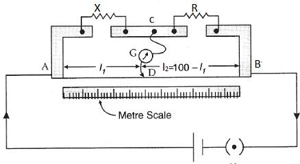
Circuit Diagram of the apparatus
Procedure: To find the resistance of a conductor
The conductor having an unknown resistance X is connected in the left gap of the circuit and a resistance box is connected in the right gap of the circuit. A battery is connected between A and B. A galvanometer is connected between C and a jockey, a movable contact, J which can slide along the bridge wire.
A suitable resistance R is taken in the box and the circuit is closed. The position of the jockey is adjusted so that the galvanometer deflection is zero.
The balancing length AJ is measured as I1 and BJ as I2 = 100 – l1. According to Wheatstone's principle, X/R = l1r/l2r; where r is the resistance per unit length of the wire AB.
Therefore X = R(l1/l2)
Thus the resistance X of the conductor is calculated. The experiment is repeated for different values of R.
The experiment can also be repeated by interchanging X and R between the gaps. If AJ = l’1 and BJ = l’2 = (100 — l’1), then,
R/X = l’1/l’2
Therefore, X = R(l’2/l’1)
The average value of X is calculated.
Note: In the calculation of X given above, end resistances being very small are neglected. There is a contact resistance at each end of the bridge wire fixed to the copper strip. These contact resistances at both ends of the bridge wire are the end resistances. But to yield accurate result the correction has to be applied for the end resistances. This correction is called end correction. The end correction can be minimized by (i) obtaining the balancing point J at the middle of the wire and (ii) repeating the experiment by interchanging X and R between the gaps.
POTENTIOMETER
It is a device to measure potential difference. It consists of a uniform resistance wire AB, usually 10 metre long, stretched on a wooden board in a zigzag manner so that each segment is 1 m long. A metre rule kept parallel to the segments helps to measure the balancing length. A jockey J sliding over the wire can make contact with any point on the wire.
Principle
An accumulator is connected in series with ends A and B of the potentiometer wire with the positive of the cell connected to the terminal A. A rheostat is also included in the circuit. This is the primary circuit.
Let r be the resistance per unit length of the wire. When the key is closed, let i be the steady current flowing through the circuit. Potential difference (fall of potential) per unit length of the wire = ir.
For a length l, the fall of potential = irl
For a steady current, pd across the wire is proportional to the length of the wire.
The positive of a cell of emf E is connected to A and the negative to a jockey through a galvanometer. This is the secondary circuit. The jockey is moved along the wire and the balancing length AJ = l, where the galvanometer shows null deflection is found out. Then,
Emf of the cell, E = P.d between A and J = irl
Therefore, E ∝ l
This is the principle of the potentiometer.
To obtain balance, the Pd between A and B should be greater than the emf E of the cell in the secondary circuit.
Experiment 1: To compare the emfs of two cells
Connections:
(a) Primary circuit
An accumulator, a rheostat and a key are connected in series between the ends A and B of the potentiometer wire. The positive of the accumulator should be connected to A.
(b) Secondary circuit
The first cell of emf E1, a galvanometer and a high resistance are connected in series between the terminal A and the jockey J. The positive terminal of the cell is connected to A.
Procedure
The primary circuit is closed. The balancing length AJ = l1is noted. Then
E1 ∝ l1
The first cell of emf E1 is replaced by the second cell of emf E2 in the circuit. Again the balancing length AJ = l2 is measured.
E2 ∝ l2
Equations (i)/(ii),
E1/E2 = l1/l2
The experiment is repeated by adjusting the rheostat. The average value of E1/E2 is calculated.
Note: If the emf E2 of the second cell is known, emf E1 of the first cell can be calculated;
E1 = E2(l1/l2)
Experiment 2: To find the internal resistance of a cell
The connections are made as shown in the diagram. A resistance box R is connected across the cell through a key K. With the key K open, determine the balancing length l1. Then the emf of the cell,
E ∝ l1
A suitable resistance R is taken in the box and the key K is closed. The pd at the terminals of the cell falls to terminal pd, ER/(R + r), where r is the internal resistance of the cell. If l2 is the balancing length then, ER/(R +r) ∝ l2
Dividing eqn (1) by (2)
(R +r)/R = l1/l2,
r = R(l1 - l2)/l2
The experiment is repeated for different values of R. It is seen that internal resistance (r) varies with the external resistance R.
Note: Emf of a cell cannot be measured using a voltmeter. When a voltmeter is connected between the terminals of the cell, a current flows through the voltmeter. So, the voltmeter measures only the terminal pd. But a potentiometer is preferred to a voltmeter to measure the emf of a cell.


