
The transmission through optical fibre can be lossy or distorted due to linear and non linear effects in the optical fibre. The linear effects can be
1. Attenuation
2. Absorption
(a) Intrinsic Absorption
(b) Extrinsic Absorption
3. Scattering
(a) Rayleigh Scattering
(b) Mie Scattering
4. Bending
(a) Microbends
(b) Macrobends
1. Attenuation
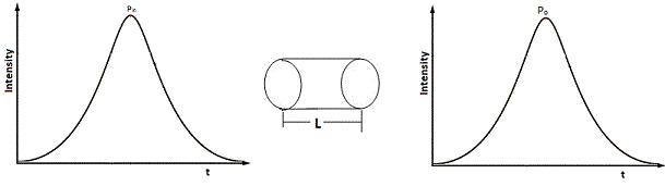
Loss of signal strength while travelling through optical fibre from transmitting end to receiving end is called Attenuation. Attenuation is directly proportional to distance travelled. Expressed in dB per km, wavelength dependent and it is inversely proportional to λ.
Power at the output is,
Po = Pine-αpL
Pin – Input Power
Po – Output Power
L – Length of fibre
α – Attenuation Coefficient
Po/ Pin = e-αpL
In(Po/ Pin) = -αpL
αp = 1/L In(Pin/ Po)
αp = 2.303/ L . log(Pin/ Po)
αdb/km = 10/L. log(Pin/ Po)
αdb/km = 4.343 αp
Attenuation loss is less in single mode fibre compared to multimode fibre. Attenuation can be due to scattering, absorption, bending and fibre connections.
2. Absorption
Absorption is defined as the portion of attenuation resulting from conversion of optical power into another energy form such as heat. It can be due to
a. Atomic structure defects of fibre material.
b. Impurities in the fibre material.
c. Basic fibre material.
Two types of absorption are:
a. Intrinsic Absorption
b. Extrinsic Absorption
Intrinsic Absorption:
Occurs in fibers made of pure silica, can happen in UV and IR regions. Absorption in UV region is due to stimulation of electron transition within the glass by higher energy excitation. Absorption in IR region is due to interaction of photon with the molecular vibrations within the glass. The oscillations or vibrations of structural units like SI-O, Ge-O causes strong absorption. Intrinsic absorption can be minimized by proper choise of core, cladding composition.
Extrinsic Absorption:
It is caused by metallic impurities such as iron, nickel and chromium introduced into the fibre material during fabrication. Water in Silica forms Silicon hydroxide (Si-OH) bonds are bonded into the glass structure and have vibrations which will result in absorption.
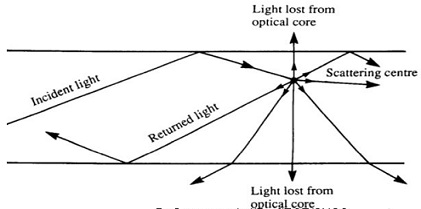
3. Scattering:
Scattering transfers optical power of one mode to another mode. Signal can get attenuated if the power is transferred to a leaky mode which doesn’t continue to propagate through the fibre but radiates out. It can be due to microscopic variations in material density, compositional fluctuations, structural inhomogenities, manufacturing defects. ‘No change in frequency due to scattering’.
Two types are
i. Rayleigh Scattering
ii. Mie Scattering
i. Rayleigh Scattering
Occurs due to material in homoginities, density and compositional variations. These r factors result in refractive index fluctuations. Attenuation due to Rayleigh scattering is inversely proportional to λ4. Mathematically Rayleigh scattering can be given by,
γR = 8π3n8P2βckTf/3 λ4 |
γR - Rayleigh scattering Coefficient
λ – Wavelength
n – Refractive Index
P – Photoelectric Coefficient
βc – Isothermal compressibility at ‘fictive temperature’, Tf (Temp at which density variations are frozen into the glass when it soldifies).
k – Boltzmann constant
à Relation between γR and transmission loss factor (transmissivity) of the fire can be given as,
Transmissivity = e- γRL
Where L – length of fibre
àAttenuation due to Rayleigh scattering, α = 10 log 1/transmissivity.
à Rayleigh scattering can be reduced by operating at the largest possible wavelength.
ii. Mie Scattering
Occurs at points where inhomogenetics is comparable in size or greater than λ/10 with the guided wavelength. This inhomoginities can be,
a. non perfect cylindrical structure
b. core cladding RI change
c. Irregularities in core, cladding interface
d. changes in fibre diameter with length
e. presence of air bubbles.
à Scattering created are in the forward direction can be reduced by
a. Removing imperfections such as non uniform fibre diameter. Presence of bubbles etc.
b. Increasing Relative RI difference to make the fibre more guiding.
c. carefully controlled extrusion and coating of fibre.
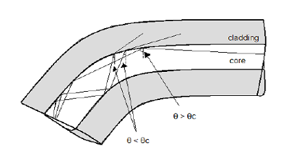
4. Bending Loss (Radiative Losses):
àRadiation loss takes place at the bends because the energy in the evanescent field in the cladding exceeds the velocity of light at the bend inhibiting the guiding mechanism.
àThe part of the light wave in the cladding that decays exponentially as a function of distance from the core is known as ‘evanescent field’.
àSince this is not possible, the optical energy in the field tail beyond Xc radiates away.
Depending on the radius of the bends, the two types are
(a) Microbending Losses
(b) Macrobending Losses
Microbending Losses:
àIf the radius of curvature is a few μm, the bend is called microbends.
àThese repetitive small scale fluctuations can be due to
i. Non – uniformities in the manufacturing.
ii. Non – uniform mechanical tensile forces by which fiber is pressed against rough surface.
iii. Non – uniform lateral pressure created during cabling of fiber.
àLoses due to this are also called cabling loss or packaging loss.
àCauses repetitive coupling energy between guided and unguided modes causing light to escape outside the fibre core
àCan be minimized by
a. Extruding a compressible jacket over fiber.
b. In single mode fiber, choose V number near cut off.
àMicro bending loss in multimode fiber is
LossM,microbend = N.h2a4/b6Δ3. (E/EF)3/2 |
Where, N – No: of humps
h – height of the hump per unit length
a – core radius
b – Fiber diameter
Δ – Relative RI difference
E – Elastic modulus of surrounding medium (Jacket)
EF – Elastic modulus of fiber.
àMicro bending loss in single mode fiber
LossS,microbend = 0.05αm K4(Fd)6(NA)4/a2 |
Where, αm - attenuation constant
K – Wave factor = 2 π/λ
A – core radius
Fd – Half of mode field diameter
Macro bending Losses:
àOccurs when the radius of curvature is larger than the fiber diameter
àAlso called large – curvature radiation loss.
àThe fiber bend radius at which the loss is maximum is called critical radius
àLoss due to macrobend can be expressed as,
Lossmacrobend = 10log([α+2]/2α[a/RΔ]) |
Where α – profile parameter
a – core radius
R – bend radius
Δ – Relative RI difference
Critical radius for multimode fiber,
Rcm = 3n12λ/4π(n12-n22)3/2 |
Critical radius for single mode fiber,
Rcs = 20λ/(n1 – n2)3/2 (2.748 – 0.996 λ/ λc)-3 |
Where, λc – cut off wavelength
Critical normalized frequency,
Vc = 2π/λc.an1(2Δ)1/2 |
λc/ λ = V/Vc
λc = Vλ/Vc = Vλ/2.405
àcan be reduced by,
a. Designing fibers with large relative refractive index differences.
b. operating at the shortest wave length possible.
Tags:
Optical Communication