
Block Diagram of FM Recording :
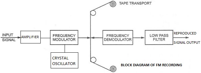
The block diagram showing the frequency modulated recording is shown in the given figure. It is clear from the block diagram that the input signal is amplified and is given to the modulator. The modulator output is shown to be supplied to the recording head:
The recording head itself will act as the play back head in most of the cases. The output c head is given to the Discriminator the F.M. demodulator. The output of the demodulator is given to a low pass filter (L.P.F.). The low pass filter eliminates the presence of the carrier and unwanted frequency components (say noise) in the output. The reproduced output can be given to a transducer.
Working :
From the block diagram it is clear that the input signal is given to an amplifier. The amplifier amplifies the signal amplitude such that the modulated signal amplitude is sufficient and is applied to the recording head to present sufficient flux variations in the air gap.
The local oscillator used is a crystal oscillator generating the carrier frequency, without any frequency deviation. As this is frequency modulation, the carrier frequency must be free from frequency deviation or frequency scintillation. The input signal frequency modulates the carrier frequency. For zero input signal the carrier frequency shall be constant and shall increase in frequency. For positive amplitudes of the input signal the carrier frequency deviates in one direction, say it increases. For negative amplitudes of the input signal the carrier frequency deviates in the opposite direction, say it decreases.
So the output of the modulator for D.C. components (no signal) is constant. It varies for all A.C. inputs. The variation in the frequency of the carrier frequency is comparative to the amplitude of the input signal. This frequency modulated signal is supplied to the recording head. So the recording head will produce flux variations corresponding to the signal variations in the air gap. The tape is passed past the recording head, with a constant speed. Hence the signal gets recorded on the tape.
During the play back, the play back head’s output is given to an F.M. demodulator, the F.M. discriminator. It converts the frequency variations to the signal amplitude variations. The output of the demodulator is given to a low pass filter, which eliminates the carrier frequency component and unwanted frequency components. In the output of the filter we have the signal information. The output of the filter can be given to the desired transducer for utilization.
Advantages of F.M recording:
The following are the advantages of F.M. recording:
1. The D.C. component of the input signal can be preserved.
2. It offers wide range of frequency response.
3. High degree of accuracy in reproduction of signal.
4. No drop out effect due to tape.
Disadvantages of F.M recording:
1. It is highly sensitive to the speed fluctuations.
2. The circuitry is complicated.
3. For best results high quality tape and high speed are to be used.
APPLICATIONS OF F.M. RECORDING:
Direct Recording System:
1. It is used in spectrum analysis of noise.
2. It is mostly used for voice signal recording.
3. It is used when maximum band width is required
F.M. Recording System:
1. Mostly used in multiplexing instrumentation systems.
2. Extensively used for recording of non electrical quantities like acceleration and pressure.
Tags:
Data Recorders