
Magnetron Oscillators:

A Magnetron Oscillator is used to generate high microwave power required in radar and communication systems. Magnetrons are cross field tubes in which the magnetic field and electric field are perpendicular to each other. All magnetrons consist of some form of anode and cathode operated in DC magnetic field which is perpendicular to DC electric field. Due to this cross field, electrons emitted from cathode moved in curved paths. If the magnetic field is strong enough the electrons will not arrive at the anode, but return to cathode itself. Thus the anode current is cut off. Magnetrons can be classified into three. They are
1. Split anode magnetron:
This type of magnetron uses negative resistance.
2. Cyclotron frequency magnetron:
This magnetron operates under the influence of synchronization between AC components of electric field and periodic oscillations of electrons in the direction parallel to the electric field.
3. Travelling wave magnetron:
This type of magnetron depends on the interactions of electrons with travelling electromagnetic field.
Cylindrical Magnetron Derivation:
Bo - Flux Density
a - radius of cathode cylinder
b - radius of anode cylinder
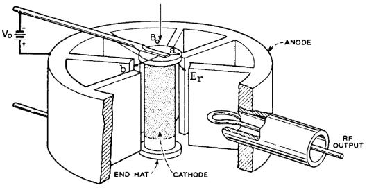 |
| Schematic Diagram of Cylindrical Magnetron |
Bo - Flux Density
a - radius of cathode cylinder
b - radius of anode cylinder
Equation of Electron Motion or Hull cut off Voltage equation:
A charged particle in motion in a magnetic field of flux density B, experiences a force that is proportional to the charge, velocity, flux density and sine of angle between velocity and magnetic flux. The general equation for the motion of electron in terms of cylindrical co-ordinates is given as,
r2(dΦ/dt) = ½ωcr2 + constant ------------------ (1)
Where ωc is the cyclotron angular frequency given by,
ωc = eBz/m
e – charge of electron
Bz – magnetic flux density
M – mass of electron
Let, r = a and dΦ/dt = 0
Therefore, Equation (1) becomes
½ωca2 + Constant = 0
Constant = -½ωca2 --------------------- (2)
Substitute equation (2) in (1)
r2(dΦ/dt) = ½ωcr2 - ½ωca2 = ½ωc(r2 - a2)
dΦ/dt = ωc(r2 - a2)/2r2 = ½ωc (1- (a2/ r2)) ---------------- (3)
The KE of electrons is given by,
½mv2 = eV
v2 = 2eV/m
considering r and Φ components of electron velocity, the above equation can be represented as,
vr2 + vΦ2 = 2eV/m
(dr/dt)2 + (r dΦ/dt)2 = 2eV/m ---------------- (4)
Let r = b
V = Vo
dr/dt = 0
Therefore the above equation (4) becomes,
(b dΦ/dt)2 = 2eVo /m -------------------- (5)
Substituting dΦ/dt from eq (3)
b2(ωc/2 (1- (a2/ r2)))2 = 2eVo /m
Substituting r = b
b2(ωc (1- (a2/ b2)))2 = 2eVo /m
b2ωc/4(1- (a2/ b2))2= 2eVo /m
b2ωc2(1- (a2/ b2))2= 8eVo /m
Substituting ωc = eBz/m
b2(eBz/m)2(1- (a2/ b2))2= 8eVo /m
b2e2/m2 (1- (a2/ b2))2 Bz2 = 8eVo /m
This magnetic field intensity is known as cut off flux density, Boc
Voc = b2e Bz2 (1 –(a/b)2)2/8m
This equation is known as ‘Hull cut-off voltage equation’
Cyclotron Angular Frequency:
The cyclotron angular frequency of cylindrical magnetron is given by,
ωc = eB/m
The period of oscillation is given by,
T = 2 π/ ωc
T = 2 πm/eB
The phase shift is given by,
Φ = 2 πm/N
Where, N is the number of cycles.
Output Power and Efficiency:
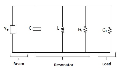
The efficiency and output power of the magnetron depend on the structure and power supply. The equivalent circuit of magnetron is,
Ye – admittance
C – Capacitance
L – Inductance
Gr – Resonator Conductance
Gl – Load Conductance
The unloaded quality factor is given by,
Qun = ωoC/Gr
The loaded quality factor is given by,
Ql = ωoC/Gr+ Gl
The external quality factor,
Qext = ωoC/Gl
The circuit efficiency, ηc = 1/(1 + (Qext/Qun))
Electronic efficiency, ηe = (VoIo – Plost) /VoIo
Where VO – Anode Voltage
Io – Anode Current or Beam Current
Plost – Power lost in the anode.