
Normal sweep generators apply their sweep voltage through the horizontal amplifier to the deflecting plates. This does not required any start signal for the sweep to generate its ramp voltage.

An advantage can be derived in displaying signals of short duration, stretched over a large area of the screen, by controlling the sweep generators output to be present only at our command. This is done by applying what is called a TRIGGER PULSE that triggers or starts the sweep voltage. The trigger pulse can be derived from the waveform under observation. A modified UJT sweep generator circuit is shown below in Figure.
 |
| Triggered Sweep Circuit |
From the figure it can be observed that this is a modification of the UJT sweep generator. A voltage divider is formed by the two resistors R3 and R4, across the supply VBB. The values of the resistances R3 and R4 are so selected that the voltage on the cathode of the diode is less than the peak voltage of the UJT, VP. The timing circuit consists of Rt and Ct which is connected to the supply. The UJT is connected as shown in the circuit, with R2 in base 2 and R1 in base 1. The diode is placed between the mid point of the RTCT combination for timing and the potential divider formed by R3 and R4.
When the supply is switched on the capacitor starts charging through the resistor Rt towards VBB till that point where the diode becomes forward biased and conducts. As the diode is conducting the capacitor CT is clamped at a voltage VD the voltage at the cathode of the capacitor. It cannot reach the voltage VP required for conduction. This is shown in the waveform. If now a negative voltage of sufficient amplitude is applied to base 2 of UJT. The peak voltage decreases momentarily and the UJT fires. Therefore the capacitor discharges through the UJT till the maintaining voltage Vmin as shown in the waveform is reached. Now the UJT switches off. Hence the capacitor again charges towards the VBB till VD where it is clamped. This process repeats as long as the supply voltage and the trigger pulses are present. The sweep waveform is as shown in the Figure. It must be noted here that the trigger pulse initiates the retrace before the sweep could be generated. Hence the part of the wave form corresponding to the retrace period will be lost. This is why we use the delay line in the vertical section of the CRO.
The block diagram of the Triggered sweep generator is shown below in figure.
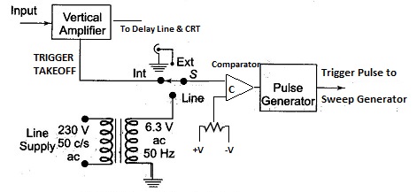 |
| Block Diagram of Triggered Sweep Circuit |
The trigger selector connects the comparator to either the output of the vertical amplifier. external trigger, or to the secondary of the low voltage transformer line. The reference level of the comparator is set by the trigger level control. The comparator gives out its output when the trigger input signal exceeds a particular value as set by the trigger level control. A schmitt trigger that follows the comparator generates negative pulses each time the comparator's output crosses the trigger level. This triggers the sweep generator to start the new sweep.
Tags:
Cathode Ray Oscilloscope