
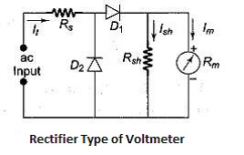
A rectifier type of voltmeter is nothing but a rectifier type of ammeter (without the current transformer) with the series resistor as connected earlier in a dc voltmeter circuit. The arrangement is shown below with a rectifier type voltmeter diagram.
(a) Working :
R1 is the multiplier resistance. D1 and D2 act as a full wave rectifier. D2 shunts the meter by-passing the current during the negative half cycles of the input voltage. The shunt across the ammeter is to bring the diode D1 into linear portion of the characteristic. During the positive half cycles of the input the diode D1 conducts and the rectified current passes through the ammeter. The average current is indicated by the meter. This can be calibrated in terms of R.M.S volts.
(b) Value of Multiplier Resistance on A.C. Ranges :
The voltmeter for alternating voltage measurement may employ a full wave bridge rectifier or a half wave rectifier with a shunt resistance across the ammeter. In either case the current that flows through the meter is the rectified alternating current.
In case of half wave rectifier the equivalent d.c value of the rectified alternating voltage will be
Edc = 0.45 x ERMS
In the case of full wave rectifier the equivalent d.c value of rectified alternating voltage will be
Edc= 0.9 x ERMS
Considering the half wave rectifier using the shunt as described in Figure, the value of the multiplier resistance can be calculated as follows :
Let Im be the full scale deflection current of the ammeter.
Rm be the internal resistance of the ammeter.
Rsh be the shunt resistance across the ammeter to bring the diode D1 into linear portions of its characteristics. Also Rsh = Rm.
RD be the forward resistance of the diodes.
E be the R.M.S. voltage applied to the test terminals.
Edc be the equivalent d.c. voltage on rectification.
The reverse resistance of the diodes being high it is assumed to be open (infinite resistance) under reverse bias.
As the shunt resistance and the meter internal resistance are assumed to be equal, to get the full scale deflection, the current that is to be supplied by the source is 2Im. The equivalent dc voltage of the applied A.C., E volts will be equal to 0.45 x E.
Therefore the total resistance of the voltmeter will be equal to:
RT = (0.45 x E)/2Im,
This total resistance consists of the series multiplier plus forward resistance of the diode D1 plus the resistance due to the parallel combination of meter resistance and shunt.
RT = Rs + RD1 + Rm Rsh/ (Rm + Rsh)
Hence, Rs = RT - (RD1 + (Rm Rsh/ (Rm + Rsh)))
This resistance Rs will be less than the value of series multiplier resistance calculated for d.c volts. This results in reduction in the sensitivity of the voltmeter in alternating volts range.
In case of full wave rectifier arrangement without any shunt arrangement across the ammeter the value of multiplier can be calculated taking the equivalent d.c. value of the alternating voltage applied to be 0.9 x E. Total resistance of the voltmeter.
RT = (0.9 x E)/Im
Neglecting the forward resistance of diodes
RT = Rs + Rm
Hence Rs = RT - Rm
This value resistance will be less than the value of the multiplier resistance for d.c voltage. So the sensitivity of the voltmeter on alternating voltage ranges will be lower than for the d.c voltage range sensitivity.
It is to be remembered here that the value of multiplier is suitable in case of sinusoidal wave forms only and does not suit for other waveforms. The following example will make the above explanation clear.
Example:
A 0-50 μA moving coil ammeter is to be used as a voltmeter to read 10 V (RMS) alternating voltage. If the internal resistance of the ammeter is 2000 Ω and the resistance of the diodes in the forward direction is 500 Ω, find the multiplier resistance and sensitivity. Assume half wave rectification and a shunt resistance across the meter. The value of the shunt resistance across the ammeter is 2000 Ω.
Solution: The meter resistance and the shunt resistance are equal. Therefore the current requirement is 5 0 μA x 2 = 100 μA
Edc = 0.45 x 10 = 4.5 V
Total resistance of the voltmeter = 4.5 V / 100 μA
= 45 kΩ
Rs = 45 kΩ - (500 + 1000) = 43.5 kΩ
Sensitivity in 10 V a.c range is
45 kΩ/ 10 V = 4.5 kΩ/V
It is clear that the sensitivity of the ammeter in d.c. volts range will be
1/50,µA = 20 kΩ/ V
Even if full wave rectifier is used and there is no shunt the value of multiplier resistance for a.c 10 V will be :
Edc = 0.9 x 10V = 9V
RT = 9 V/50 µA = 180 kΩ
Rs = 180 - 2.5 kΩ = 177.5 Ω
Sensitivity 180 kΩ/ 10 V = 18 kΩ / V
The sensitivity on dc volts range is 20 kΩ / V. So the multiplier value is low compared to the dc value.
(c) Factors Affecting the Performance of Rectifier Instruments :
The performance of the rectifier type voltmeter / ammeter is affected by the following factors :
1. Waveform
2. Rectifier resistance
3. Temperature
4. Capacitance of rectifier.
1. The calibration of the rectifier type voltmeter is valid for sinusoidal voltages only. This is because of the fact that the calibration is done under sinusoidal voltage and the scale of the instrument must be marked in terms of 1.11 times the actual current measured. Thus the scale indicates R.M.S. value of the voltage measured. Number of other wave forms having the same average value may have R.M.S. value that may considerably vary. In all these cases also the ammeter / voltmeter will indicate 1.11 times the average value. This results in errors.
3. The rectifying element i.e. diode has its forward resistance, which varies with temperature. Hence the instrument gives error. Using copper resistance as a part of the multiplier resistance compensates this error. When large temperatures are involved the instrument must be enclosed in a temperature controlled enclosure.
4. Rectifier offers a small capacitance. The reactance of this capacitor becomes low at high frequencies. Therefore the rectifier ceases to function as a rectifier at frequencies where its reactance is considerably low. This results in a low voltage indication in the instrument. The error is as large as 0.5 percent per kHz in frequency.
(d) Applications and Limitations of Rectifier Type Instruments:
Rectifier type of instruments is sensitive. They can be used for measurement of current and voltage within audio frequency range. They are useful in measuring low values of voltage and current, especially when the source impedance is high.
The rectifier type of instruments is not suitable even at high audio frequencies and for frequencies beyond audio frequency range. Because of the capacitance of the rectifier, inductance of the moving coil, the instrument fails at high frequencies indicating low value of reading.
Tags:
Multimeters