
Though there are convenient basic movements for measuring the current in the ranges, there will be situations where current ranges far greater than the standard ranges will be required for measurement of current. In such cases specially made ammeters will not be used. One of the available basic ammeter will be taken and it will be provided with the 'shunt resistance'. Thus any basic ammeter's range can be extended to the, required full scale deflection.

Therefore
(a) Calculation of the Value of Shunt Resistance:
Let us take an ammeter whose basic range (full scale deflection) is lm A.
Let its range be extended by 'N' times making the new full scale deflection after extension to be equal to I A.
The basic meter can take only a current of Im A. So the excess of current is (I — Im) A. This current must not be allowed to flow through the basic meter. It should he provided with a by pass path. It is for this purpose we use a shunt resistance.
Let the basic meter have a resistance of R ohm.
The Figure, illustrates the methods of connecting the shunt resistance to the basic ammeter.
From the figure, the current required to be allowed through the shunt resistance is Ish. I, is the total full scale deflection current required to be measured. Im is the current the basic meter can measure. The shunt resistance is connected in parallel (in shunt) with the basic meter. Hence irrespective of the currents flowing through the shunt resistance and the meter (with internal resistance Rm) the voltage drop across the two is the same.
Therefore
Rm x Im = Rsh x Ish
We know that Ish = I – Im
Rsh = RmIm/Ish
Substituting the value of Ish
Rsh = Rm.Im/(I - Im)
Dividing the Nr and Dr on the right hand side by Im
Rsh = Rm/([I/Im]-1)
I/Im = N, the number of times we increase the range.
N can be termed the multiplication factor. Hence the value of shunt resistance is:
Rsh = {Rm/ (N - 1)}Ω
Using a value of shunt resistance calculated as above the range of the ammeter can be extended. It is to be noted here that the shunt resistance is lower in value of its resistance by N - 1 than the value of ammeters internal resistance. Hence the current in shunt will be of the same ratio, providing the required by pass path for the excess current.
(b) Construction of Shunt Resistances:
The following are the requirements of a shunt resistance
1. The temperature coefficient of the shunt resistance must be low.
2. The value of shunt resistance should not vary with time.
3. When carrying the current the shunt resistance should not have excessive temperature rise.
4. The thermal electromotive force must be low.
The wire commonly used for winding shunt resistances is 'manganin’. For alternating current circuits we use "constantan". Constantan has high thermal emf. As the thermal emf is unidirectional it will be ineffective in AC circuits.
Shunt resistances are wound on strip type insulated formers. The resistance wire usually is provided insulation with silk sleeving. The shunt resistances will be housed in the same casing of the ammeter provided the multiplication factor is low. Shunts for heavy currents are externally connected. The construction of shunts for heavy currents is also different. Heavy current type shunts are made out of evenly spaced sheets of resistive material made into a block of heavy copper on either side of the sheets. The constructional details of the above two types of shunt resistances are shown below.
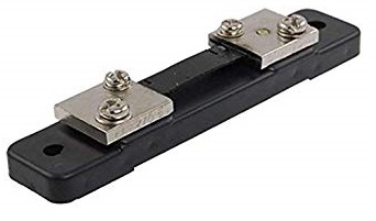 |
| Shunt Resistor |
(c) Determination of Internal Resistance of Ammeters:
It may not be always possible to know the internal resistance of the ammeter from the data sheets of the manufacturer when such sheets are not available. In order to find the internal resistance which is useful data in finding the shunt value, the following method is used in laboratories. Internal resistance should not be measured with ohm meter.
This method is termed half deflection method. The ammeter whose internal resistance is to be found will be connected in series with a large resistance and a battery. The value of the resistance will be adjusted to get full scale deflection in the meter.
Then a decade resistance box is to be connected across the ammeter. When the resistance value of the decade resistance box is zero, the ammeter reads zero. This is because the total current is diverted through the zero resistance of the decade box. The decade resistance box will be adjusted to see that the ammeter reads half the full scale deflection. Now the magnitude of current flowing through the meter and the decade box is the same. Hence the value of resistance indicated by the decade resistance box will be equal to the internal resistance of the ammeter.
The meter resistance obtained using this method will be fairly correct provided that the series resistance used to get the full scale deflection in the first step is a high resistance compared to the meter resistance and introduction of the shunt decade box does not introduce considerable change in current.
Tags:
Multimeters