The method of process control described by the term direct digital control (DDC) applies to those cases in which digital logic circuits or a computer are an integral part of the loop. In figure 1, we see a block diagram of this approach to processing. Essentially, the evaluation and controller function is taken over by digital logic circuits or programming of a computer. We distinguish these two approaches to DDC by calling logic circuit methods hardware program controlling and computer methods software program controlling. Figure 2 shows how the temperature-control problem defined earlier is implemented by DDC. The control function; set point, and deviation about all nominal are all defined by the program.
Direct digital control has the capacity to control multivariable processes with interaction between elements. This approach is gaining in acceptance as the reliability of computers improves and backup methods are being developed to avoid process shutdown because of a computer failure. The development of the so-called computer on a chip in the form of a single integrated circuit (IC) microprocessor has given considerable impetus to the use of DDC.
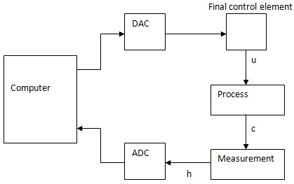 |
| Figure 1. Block Diagram of a Process-Control Loop which is Under Computer Based, Direct Digital Control (DDC) |
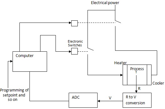 |
| Figure 2. Implementation of the Problem using a computer. |
