
Gray code was invented by Frank Gray of Bell Labs in 1947. He called his code as reflected binary code. Later others started calling it as Gray code. This code has also come to be known as mirror code. Both the names, viz., reflected binary code and mirror code, stem from its mirror-reflection property. The main features of the Gray code are:
• It is a binary code just like to the conventional binary code.
• The code can be constructed using its mirror-reflecting property.
• Adjacent numbers of the code differ in one bit-position only. This is illustrated in Table 1.26, which shows entries of decimal numbers 0 to 4, and their equivalents in the conventional binary and the Gray-code binary. In columns 2 and 3 of Table 1.26, we have highlighted the positions in which adjacent numbers differ from each other using bold fonts. It can be seen from column 2 that adjacent numbers in conventional binary may differ from each other in one or more one bit positions. For example, 0011 (= 3) and 0100 (= 4)differ from each other in three bit positions.
Now, inspection of column 3 of Table 1.26 shows that adjacent numbers in the Gray code differ from each other only in one bit position. For example, 0010 (= 3) and 0110 (= 4) differ from each other only in the second bit position from the left. This important property of Gray code has many practical applications. The foremost among these is its use in logic simplification using the K-map and Quine-Mccluskey methods. It also finds extensive use in error-detection and correction codes.
Table 1.26 Decimal, conventional binary and Gray-code numbers
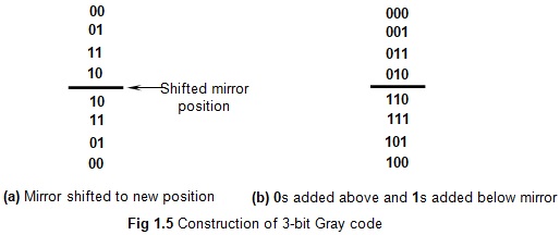
The principles used in the construction of 2-bit Gray code may be extended to get any n-bit (where n is a power of 2) Gray code. Figure 1.5(a) and (b) show the construction of a 3-bit Gray code. As in the 2-bit case, in the case of 3-bit Gray code, we shift the mirror to the new position below 10 and write the reflected code words below the mirror as shown in Fig. 1.5(a). After writing the reflected code words, as in the previous case, we add one 0 to each of the code words above the mirror one 1 to each of the code words below the mirror as shown in Fig. 1.5(b). Table 1.28 shows the actual form of the 3-bit Gray code, after the removal of the mirror. Extending the principles, we draw the 4-bit Gray code as shown in Table 1.29. it may be noted that Gray code is not a weighted code. But it finds applications because of its third feature (see Section 1.15).
• It is a binary code just like to the conventional binary code.
• The code can be constructed using its mirror-reflecting property.
• Adjacent numbers of the code differ in one bit-position only. This is illustrated in Table 1.26, which shows entries of decimal numbers 0 to 4, and their equivalents in the conventional binary and the Gray-code binary. In columns 2 and 3 of Table 1.26, we have highlighted the positions in which adjacent numbers differ from each other using bold fonts. It can be seen from column 2 that adjacent numbers in conventional binary may differ from each other in one or more one bit positions. For example, 0011 (= 3) and 0100 (= 4)differ from each other in three bit positions.
Now, inspection of column 3 of Table 1.26 shows that adjacent numbers in the Gray code differ from each other only in one bit position. For example, 0010 (= 3) and 0110 (= 4) differ from each other only in the second bit position from the left. This important property of Gray code has many practical applications. The foremost among these is its use in logic simplification using the K-map and Quine-Mccluskey methods. It also finds extensive use in error-detection and correction codes.
Table 1.26 Decimal, conventional binary and Gray-code numbers
Decimal number | Conventional binary equivalent | Gray-code equivalent |
0 1 2 3 4 | 0000 0001 0010 0011 0100 | 0000 0001 0011 0010 0110 |
Construction of Gray code
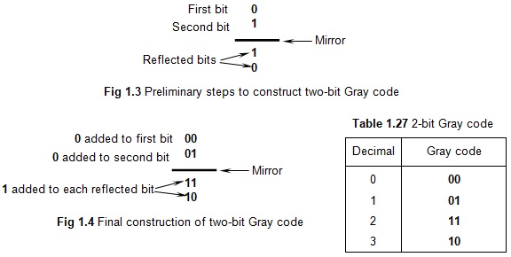
Gray code can be constructed by its mirror-reflection property. For example, a two-bit Gray code can be constructed as illustrated below. First we write 0 and then immediately below it write 1. Then we draw a horizontal line below bit 1 and then write the bits 1 and 0 below this line in that order, assuming the horizontal line to act as a mirror. Thus, we get the structure shown in Fig. 1.3.
Now, add one 0 each to the bits above the mirror-line and one 1 each to the bits below the mirror-line as demonstrated in Fig. 1.4. Table 1.27 shows the 2-bit Gray code after removal of the mirror.
Table 1.28 3-bit Gray code
Decimal | Gray code |
0 1 2 3 4 5 6 7 | 000 001 011 010 110 111 101 100 |
Table 1.29 4-bit Gray code
Decimal | Gray code | Decimal | Gray code |
0 1 2 3 4 5 6 7 | 0000 0001 0011 0010 0110 0111 0101 0100 | 8 9 10 11 12 13 14 15 | 1000 1001 1011 1010 1110 1111 1101 1100 |
nice thank you
ReplyDelete