
Construct a generator matrix and write all the code words of a (6, 3) LBC.

 Now, we combine Eqs. (1.6) and (1.7) as shown in Eq. (1.8) to yield the desired matrix G.
 We perform matrix multiplications as a row × column operation and then add the resulting bits using modulo-2 addition. It may be remembered that since the fist 3 elements in the G matrix are the identity elements, and hence the multiplication of [D] × [I] = [D] itself. So in all these cases, we only need to perform the [D] × [P] operation. Thus, we get
In the computation shown above, symbol represents modulo-2 addition. As shown in Eq. (1.10), modulo-2 addition yields the bits 0, 1, and 1, which are the parity bits. The resulting code word C1 is shown in the combined form using bold fonts as 001011. In a similar way, we find code vector C2:
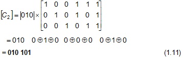 We now perform the computation of [C7] = [D7][G]. Thus
 We notice that parity bits in code vectors C1, C2 and C7 are, respectively, 011, 101, and 001. We also notice that parity word 011 is always associated with data word 001. Similarly, parity word 101 is always associated with 010, and 001 is always associated with 111. We thus find that to each of the data word, a unique set of parity bits are added and, as stated earlier, it is this uniqueness that helps in the recovery of original data from noise-corrupted data. It may be noted that code vectors C3 to C7 can be similarly determined by using the respective data vectors and the G matrix. The reader is advised to determine these code vectors.
Solution: Following the rules given above, we first construct G as given below. From definition, we have. From definition, we have
[G]k × n = [ I ]k × k [P] k × n ‒ k (1.5)
We now construct G based on Eq. (1.5) and the rules given above and the result is shown in Eq. (1.6). In Eq. (1.6), we first construct the 3×3 I matrix. As shown in Eq. (1.6), all the diagonal elements of I are 1s; all of the rest are 0s.
After constructing I, we proceed to form the P (parity) matrix as a k × (n ‒ k) = 3 × 3 matrix. In this matrix, no column must have a single-1 entry and no column must have all-0 entries. Obeying this rule, we have as the first-column elements of P the set of numbers 110. For the second column, we have chosen 101, and for the third column, we have 111. Equation (1.6) gives [P].
With k = 3, the data vectors are the binary numbers from 000 to 111. Of these, it is quite common to avoid the combination of 000. The rest of the data vectors will give finite code words by the multiplication of D and G as per the rules of Eq. (1.1). Designating data vectors D1 = 001, D2 = 010, and so on, we now compute code vectors C1, C2, and C7. Let us first determine the code word corresponding to the data vector D1 = 001. For this, we write Eq. (1.9) as given below:
[C1] = [D1][G]
In the computation shown above, symbol