
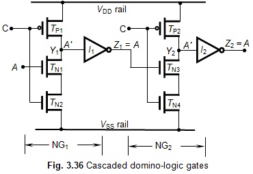
A problem with the dynamic logic is its limitation in cascading several stages. Domino logic, a modification of the dynamic logic, can be used to cascade several stages. The configuration of a domino-logic multiple-inverter gate is shown in Fig. 3.36. It can be seen from Fig. 3.36 that the circuit is the same as that of the dynamic logic gate with the addition of a CMOS inverter at the output. The addition of the inverter makes the domino logic to produce double inversion (i.e., one by the main transistor block, and the other by the inverter). Hence, only non-inverting gates are available in the domino logic system.
 Advantages of Domino Logic Gates
The working of the circuit shown in Fig. 3.36 can be explained as follows. As in the case of the dynamic-logic NAND gate, here also, when the C = 0, both the NMOS inverter blocks NG1 and NG2 are in the disabled conditions. At this time, both the PMOS transistors TP1 and TP2 are in the ON condition and the outputs Z1 and X2, respectively, of NG1 and NG2 are at +VDD (≡ logic 1). These outputs Y1 and Y2, will be inverted by the respective CMOS inverters of I1 and I2 to give their outputs Z1 = Z2 = 0.
Now, when the C = 1, NMOS transistors TN2 and TN4 get turned-on, and PMOS transistors TP1 and TP2 get turned-off. The outputs Y1 and Y2 are now dependent on the input A only. If A = 1, then Y1 = A' = 0 and Z1 = A = 1. But, if A = 0, then the output Y1 = 1, and Z1 = 0. This produces double-inversion operation by gate NG1. It may be observed that this operation is repeated by gate NG2 to give its output Z2 = A. We thus notice that both the gates produce double inversions.
The main aspect in the operation of the domino gate is that, initially as in the case of the dynamic logic, the load capacitor CL is pre-charged to +VDD through the PMOS transistor. When transition occurs due to the pulse input A, the output Y changes first. The CMOS inverter will then invert this to produce transition in the output Z. The inverter thus ensures that only one transition occurs for single-trigger inputs at A in the case of a singe-gate system.
Now, suppose we cascade two such domino-logic inverter gates, as shown in Fig. 3.36. With a trigger input, Gate NG1 produces the required transition, and then after the stipulated propagation delay, Gate NG2 produces the final transition.
If several such stages are cascaded in this fashion, the transition takes place one after another, just like thin wooden planks or playing cards fall in a domino. It may be noted that a domino is a special arrangement of several playing cards. In this arrangement, when we give a small push to the first card to the right (or left, depending on the domino arrangement), it falls onto the second card which in turn falls onto the third card and so on in that order. This is called the falling of the domino.
Domino logic has the following advantages:
1. Domino logic structure has much smaller chip area than CMOS structure.
2. Since each gate has an inverter at its output, only one transition will take place for each triggering, as stated before. This avoids glitches (sudden unwanted transitions).
3. Operating speeds are increased due to reduced value of load capacitance.