
The signals requesting the microprocessor to perform a particular task or work, send by an external device is known as interrupts. For transferring data between the peripheral and the microprocessor, interrupts are mainly used.Here we can discuss about interrupts in 8085 notes. The interrupts are checked by the microprocessors always at the 2nd T-state of last machine cycle. If an interrupt occurs, it accepts the interrupt and sends the INTR’ signal to the peripheral. The microprocessor executes an interrupt service routine (ISR) stored in memory. It returns to the main program by RET instruction, after the ISR is executed. The interrupt process is shown in figure.
 |
| Interrupt process |
Types of Interrupts:
There are six types of Interrupts in 8085. They are,
1. Hardware interrupts
2. Software interrupts
3. Maskable interrupts
4. Non-Maskable interrupts
5. Vectored interrupts
6. Non-vectored interrupts
Hardware interrupts: These interrupts are given by the peripheral devices to the interrupt pin (hardware) of the microprocessor. Hardware interrupts are also called external interrupts.
Software interrupts: These interrupts are internally generated within the microprocessor using software instructions. Software interrupts are also called internal interrupts.
Maskable interrupts: These external interrupts can be delayed or rejected by the microprocessor.
Non-maskable interrupts: These external interrupts cannot be delayed or rejected by the microprocessor. Non-maskable interrupts are used for handling emergency situations.
Vectored interrupts : When the address of the Interrupt Service Routine (ISR) is fixed within the microprocessor itself, then the interrupt is called Vectored interrupt.
Non-vectored interrupts : When the address of the Interrupt Service Routine (ISR) is supplied by the peripheral device, then the interrupt is called Non-vectored interrupt.
8085 interrupts
In 8085 microprocessor, there are 5 interrupts as shown in figure.
1. TRAP
2. RST 5.5
3. RST 6.5
4. RST 7.5
5. INTR
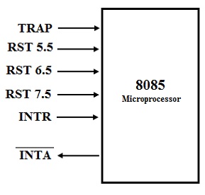 |
| 8085 Interrupts |
Notes: In additional to these hardware interrupts, 8085 microprocessor has eight software interrupts. The RESTART instructions RST 0 to RST 7 are software interrupt instructions.
Interrupt priority:
The microprocessor can respond to only one interrupt at one time. When multiple (more than one) interrupts occur simultaneously, the microprocessor will service the interrupts in their fixed priority order. Interrupt having the highest priority level will be serviced first. In 8085, TRAP interrupt has the highest priority and INTR has the lowest priority.
TRAP
• This interrupt can be considered as a non-maskable interrupt. Any mask or interrupt enable cannot affect this.
• It is a vectored interrupt. The interrupt vector address is 0024H.
• TRAP has the highest priority level.
• We can say that TRAP interrupt is level and edge triggered. This means that till the acknowledgement, the TRAP must go high and remain high.
• In emergency situations like sudden power failure, it executes an ISR and sends the data from main memory to backup memory.
RST 7.5
• The RST 7.5 can be considered as a maskable interrupt.
• It is a vectored interrupt. The interrupt vector address is 003CH.
• It has second highest priority.
• It is edge triggered. ie. Input attains at high and no need to retain the high state until it is recognized and acknowledged.
RST 6.5
• The RST 6.5 interrupt is a maskable interrupt.
• It is a vectored interrupt. The interrupt vector address is 0034H.
• It has the third highest priority.
• It is level triggered. ie. Input goes to high and stays high until it is recognized and acknowledged.
RST 5.5
• The RST 5.5 interrupt is a maskable interrupt.
• It is a vectored interrupt. The interrupt vector address is 002CH.
• It has the fourth highest priority.
• It is level triggered. ie. Input goes to high and stays high until it is recognized and acknowledged.
INTR
• INTR is a maskable interrupt.
• It is a non- vectored interrupt. After receiving INTR’, the peripheral has to supply the address of
• It has the lowest priority.
• It has the lowest priority.
• It is a level triggered. ie. Input goes to high and it is necessary to maintain high state until it is recognized and acknowledged.
Process of INTR interrupt
1. With the use of the EI instruction, the interrupt process should be enabled.
2. Whenever an instruction is executed, the 8085 checks for an interrupt signal.
3. If INTR is high, the microprocessor completes current instruction, disables the interrupt and sends INTR’ signal to the peripheral device.
4. INTR' allows the peripheral device to send an RST instruction through data bus.
5. Upon receiving the INTR’ signal, the microprocessor saves the memory location of the next instruction on the stack and the program is transferred to ‘call’ location (ISR Call) specified by the RST instruction.
6. Microprocessor executes the ISR.
7. Within the program, In order to enable the further interrupt, ISR must include the ‘EI’ instruction.
8. The RET instruction at the end of the ISR retrieves the return address from the stack and the program is transferred back to main program which was interrupted.
Instructions for Interrupts handling in 8085 microprocessor:
There are four instructions available for interrupts handling. They are,
1. DI (Disable Interrupt)
2. EI (Enable Interrupt)
3. SIM (Set Interrupt Mask)
4. RIM (Read Interrupt Mask)
DI (Disable Interrupt)
This instruction resets the Interrupt Enable Flip-flop inside the microprocessor. All the interrupts except the TRAP are disabled.
EI (Enable Interrupt)
Inside the microprocessor, this instruction sets the Interrupt Enable Flip-flop also all the interrupts are enabled.
SIM (Set Interrupt Mask)
This instruction is used to selectively mask (disable) and unmask (enable) RST 7.5, RST 6.5 and RST 5.5 interrupts. For serial data output, we can use this instruction. The SIM the instruction uses the accumulator contents for masking and unmasking the interrupts.
RIM (Read Interrupt Mask)
This instruction is used to read the status of RST 7.5, RST 6.5 and RST 5.5 interrupts like pending and enable / disable details. This instruction is also used for reading the serial data. When the RIM instruction is given, the microprocessor loads the details into the accumulator.
Summary of 8085 interrupts
Interrupt | Vector address | Priority | Type |
TRAP | 0024H | 1 (highest priority) | Hardware interrupt Vectored interrupt Non-maskable interrupt |
RST 7.5 | 003CH | 2 | Hardware interrupt Vectored interrupt Maskable interrupt |
RST 6.5 | 0034H | 3 | Hardware interrupt Vectored interrupt Maskable interrupt |
RST 5.5 | 002CH | 4 | Hardware interrupt Vectored interrupt Maskable interrupt |
INTR | - | 5(lowest priority) | Hardware interrupt Non - Vectored interrupt Maskable interrupt |
RST instruction | RST 0 – 0000H RST 1 – 0008H RST 2 – 0010H RST 3 – 0018H RST 4 – 0020H RST 5 - 0028H RST 6 – 0030H RST 7 – 0038H | - | Software interrupt Vectored interrupt Maskable interrupt |
Tags:
Microprocessors