
RF Voltage Measurement
Measurement of radio frequency voltage is difficult especially when the magnitude is very small and the frequency is very high. Naturally when small magnitudes are to be measured, we certainly need amplification of the signal, that too at the signal frequency.
Radio frequency signal amplification is complicated and requires special devices, and has several restrictions on the component size, orientation, and shielding is very important. In spite of all the precautions taken the bandwidth restriction again poses a problem. Stability of the gain of the amplifier is yet another problem. For accurate measurement care is to be taken in the design of the instrument considering all the above constrains.
R.F. millivolt meter can be either of the amplifier rectifier type or the rectifier amplifier type. thee amplifier rectifier type again can be the average reading type, peak reading type or true R.M.S. reading type.
In amplifier rectifier type of instrument initially the radio frequency signal will be amplified in a wide band amplifier. The output of the amplifier will be used in a detector to obtain an indication in the indicating instrument, which reads the value of the input voltage by proper calibration of the instrument.
In the rectifier amplifier type of radio frequency voltage measurement, the input signal will initially be rectified. The rectified D.C. will be amplified in a D.C. amplifier. The output of the D.C. amplifier will be connected to an indicating instrument which will be calibrated in terms of the input signal.
In this blog the following topics are covered :
Classification of amplifier rectifier type of A.C. Millivoltmeters
Principle of working of the amplifier rectifier type of A.C. Millivoltmeter
Applications of amplifier rectifier type of A.C. Millivoltmeter
Principle of working of the Rectifier amplifier type of A.C. Millivoltmeter
Types of Probes used with the rectifier amplifier type of instrument
Applications .
Amplifier Rectifier Type A.C. Millivoltmeter
In this type of instrument the input signal will first be amplified in a wide band amplifier. The output of the wide band amplifier will be used in a rectifier to get a D.C. output which will be indicated in an indicating instrument.
(a) Classification
Depending on the type of rectifier arrangement used in the circuit we have three types of A.C. millivoltmeters as listed below:
(i) The average reading type
(ii) The peak reading type
(iii) The true R.M.S. reading type
(i) The Average Reading Type
In this type the dial calibration will be made multiplying the average output of the rectifier by the form factor 1.11, for the sinusoidal waves. For square wave inputs the reading will be more than the true R.M.S. value by 11%. For triangular wave inputs the reading will be less than the true R.M.S. value by 4%.
(ii) The Peak Reading Type
In this type the detectors response will be quick for increasing amplitudes of the input signals. i The response will be slow for the decreasing amplitudes. As it is the peak detector that is employed, it "holds" the peak indefinitely. Practically a suitable decay will be obtained by properly choosing the time constant selecting the value of capacitor and load resistor in the peak detector.
(iii) The True R.M.S. Reading Type
The true R.M. S. type indicates the R.M.S. value of the input signal for any type of waveform. It is for this purpose the amplifier and the detector must be confined to their linear region of operation. The true R.M.S. indication will be specified for a given maximum value of "crust factor", which is less than 5. The crest factor will be more than 5 in special cases like the pulse train that have a low duty ratio. Therefore the true R.M.S. meter is generally specified for the crest factor value of 5, for an input signal having an R.M.S. value that equals the full scale deflection.
(b) Description of the Block Diagram
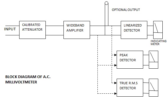
The block diagram of the a.c. millivoltmeter is shown in Figure. From the block diagram it can be seen that the input signal to be measured will reach the wide band amplifier through a calibrated attenuator.
The output of the wide band amplifier is supplied to the linearized detector. The output of the detector is given to the indicating instrument. Two more detectors which are optional have been shown in the block diagram to indicate the three types of arrangements that can be hand in this type of instrument. The two other blocks of detectors are shown to have been connected in dotted lines. The choice of the detector is optional. Further the output of the wide band amplifier can be terminated over a socket as an optional output terminal, as is shown in the block diagram.
 |
| Block Diagram of AC Millivoltmeter |
(c) Measurement Method
The zero setting of the indicating instrument is to be adjusted correctly to zero after the normal warming time of the instrument. The signal input is applied to the input terminals. The range switch is initially is to be set to the largest range. By adjusting the range switch, a reading close to the full scale reading is to be obtained which accurately gives the magnitude of the input signal.
(d) Applications
Noise analysis
Turbulance studies
R.M.S. power measurement in power systems using thyristor.
(e) Limitations
The rectifier amplifier type of A.C. millivoltmeters performance is limited by the bandwidth of the amplifier. They can be used up to around 5 MHz, beyond which their accuracy will be poor.
Tags:
AC Millivoltmeter
Specifications and significance of AC Millivolt meter
ReplyDeleteIt's urgent
See, http://www.electronicsandcommunications.com/2019/05/rectifier-amplifier-type-ac.html
Delete