
A voltmeter is basically an ammeter. Every ammeter can withstand a voltage given by the product of its full scale deflection current and its internal resistance. Thus a 0 – 50 micro amperes meter (ammeter) with an internal resistance of 2000 Ω can measure a voltage of 100 mV. In order to obtain the required full scale deflection in volts, a series resistance called the multiplier resistance is to be connected in series to the ammeter. The ammeter and the multiplier resistance in combination will make a voltmeter. The multiplier limits the current to the full scale deflection current of the ammeter when the full scale deflection voltage is impressed across the combination. The arrangement is shown in Fig.

 |
Ammeter with a series resistance to work as a voltmeter |
(a) Value of Multiplier Resistance Required to Convert an Ammeter into a Voltmeter:
Let Im be the full scale deflection current of the given ammeter.
Rm be the internal resistance of the given ammeter.
Rs be the value of the multiplier resistance.
v be the voltage across the ammeter for the current Im.
V be the full scale voltage to which the ammeter has to respond.
From figure,
v = Im.Rm
V = Im(Rm + Rs)
Rs = (V/Im) – Rs --------------------------- 1
In an alternative way let V/v = Im (Rm+Rs)/Im Rm = 1+ (Rs/Rm)
Therefore Rs = (N-1)Rm ------------------------ 2
Either formula 1 or 2 can be used to find the value of the multiplier resistance.
From the above discussion we note that the multiplier required to measure a voltage N times the basic voltage range of the ammeter is (n-1) times the basic voltage range. If N = 20, the multiplier resistance value is 19Rm.
(b) Construction of Multiplier Resistances:
A multiplier resistance must have the following characteristics.
1. Its resistance should not change with tune.
2. Its resistance should not change with temperature.
3. It should not offer inductance.
Wire wound resistances are usually employed as multiplier resistances. They use manganin and constantan as the wire material. These wire wound resistances of the low and medium power type are arranged in the casing of the instrument itself. When the voltages to be measured are large, multiplier resistors are mounted outside the casing to prevent heat inside the instrument casing.
Example:
Convert a 0 to 1 mA ammeter with internal resistance of 50 Ω to give a full scale deflection corresponding to 100 V.
Solution:
Draw the circuit arrangement and calculate the power dissipation in the multiplier resistance.
Basic ammeter's range = 0 to 1 mA
Meter internal resistance = 50 Ω
Required full scale deflection = 100 V
Value of multiplier resistance = Rs
= (V/Im) - R
= (100/1 x 10-3) - 50
= 99,950 ohm or 99.95 K Ω
Power dissipated in multiplier resistance = (1 mA)2 x 99.95 KΩ
= 0.09995 W.
(c) Multi Range Voltmeters:
Using a basic ammeter number of voltage ranges can be obtained providing number of multiplier resistances in series with the basic meter. They may be provided on individual basis or can also be provided using a potential divider.
The individual multiplier resistance method is shown below in Fig.
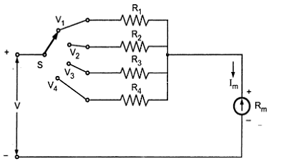 |
| Multi Range Voltmeter |
The basic ammeter is provided with a rotary switch. This switch connects the four multiplier resistances in series to the ammeter depending on the position of the switch. Thus the switch works as a range selector. The four values of multipliers can be obtained as explained. The multiplier resistances R1, R2, R3 and R4 will be connected in the 1st, 2nd, 3rd and 4th positions of the rotary switch respectively in series to the ammeter. Thus the four positions of the switch will give four voltage ranges, using the same basic ammeter. In this method of connection we need four individual multiplier resistances to cover the four voltage ranges.
An arrangement providing a common resistance with properly designed taps can be used to offer four voltage ranges with a basic ammeter is shown below.
In the arrangement shown above four voltage ranges are offered by the four taps on the multiplier resistor. The voltage ranges offered are V1, V2, V3 and V4 with increasing voltages respectively. The values of resistors (resistance tapes on single multiplier resistor) are R1, R2, R3 and R4, respectively. The values of these resistors are calculated as follows.
Let Im be the meter current (FSD)
Rm be the internal resistance of the ammeter.
R1 = (V1/lm) - Rm
R2 = (V2/Im) - (Rm + R1) ... as the meter internal resistance along with the first value of multiplier resistance will now be the internal resistance for the second voltage range.
R3 = (V3/Im) - (Rm + R1 + R2) ... for the same reason as mentioned above.
R4 = (V4/Im) - (Rm + R1 + R2+ R3) ... for the same reason.
It can be seen that the only difficult value of resistance out of the four will be R1, which is to be manufactured. The other resistances will be commercially available, if the multiplier resistance is to be made up of four individual resistances. If a taped resistor is used the taps are to be adjusted to the value obtained by calculation.
The negative terminal of the ammeter will be the common one for all measurements of voltages. The taps will be terminated over terminal posts (binding posts) indicating the voltage obtainable from that terminal. Any of the four ranges can be used at a time for measurement taking the required voltage terminal as + ve test terminal and the common terminal as the -ve test terminal. The advantage of this method is that there is no switch and a single taped resistor may be used.
(d) Sensitivity of a Voltmeter:
The sensitivity of a voltmeter is expressed in ohm/volt. It is the resistance required in series of the ammeter to give a full scale deflection of 1 volt. The more the ohm/volt, the value of resistance required in series to the ammeter, the more sensitive the voltmeter is.
Tags:
Multimeters