
(a) Description of the Circuit of Rectifier Type of Ammeter:
The circuit generally employed in rectifier type of ammeters is explained as follows. It uses two diodes D1 and D2. They work as full wave rectifier. The moving coil is connected in such a way that it carries only half of the rectified current. A shunt resistance Rsh is connected across the moving coil meter. This draws more current from the diode Di and keeps the operating point of the diode D in the linear portion of the characteristic.
(b) Working:
During the positive half cycles of the input the diode D1 conducts. Hence the rectified current flows through the ammeter. As there is a shunt resistor Rsh across the ammeter the operating point of the diode D1 will be in the linear portion of its characteristic. So variation in resistance during conductive periods of the diode is minimised in this arrangement. D2 conducts during the negative half cycles. This shorts the meter during the negative half cycles. Therefore it prevents application of the reverse current through diode D1 flowing through the ammeter. The deflection given by the ammeter is the average current flowing through it. All alternating instruments are calibrated in R.M.S. value. So the reading is to be multiplied by form factor and the scale is to be calibrated.
(c) Full Wave Bridge Rectifier:
Bridge rectifier also can be used for the measurement of current (ac) using a moving coil ammeter. A circuit showing the arrangement is given under Figure.
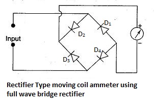
The circuit shown above is using a full wave bridge rectifier for rectification. The two test terminals are connected to the diagonal points of the bridge rectifier. The meter is connected in the place of the null detector. The input current wave form and the wave form of the rectified current are shown below under Figure.

Diodes D2 and D4 conduct during the positive half cycle of the wave form and diodes D1 and D3 conduct during the negative half cycle. The average rectified current flows through the ammeter. Therefore it indicates only the average value of the current. The scale is to be multiplied by form factor and is to be calibrated in R.M.S. value.
Extension of Range and Shunts:
Usually rectifier ammeter uses a current transformer whose primary carries the current to be measured. The rectifier and the moving coil ammeter will be connected to the secondary. Shunts cannot be provided. The reason is that the proportion of the total current passing through the meter will be varying with the total current because of change of rectifier resistance with current.
Tags:
Multimeters