
(a) Description of the Circuit of Electronic Voltmeter Using FET:
The circuit is shown in Figure. It consists of the input attenuator, range selector switch and two FETs with associated components as shown in the circuit. The two FETs with the associated components shown as a difference amplifier. The difference in their inputs is indicated by the meter connected in the source circuit.
The input attenuator consists of five resistors connected as a potential divider. Therefore there can be five ranges. The ranges are selected by a selector switch. The pole of selector switch is connected through the gate limiting resistance to the gate of the first FET, F1. The drain terminals of the two field effect transistors are connected directly to the d.c. supply. The source terminals are provided with three resistors R1, R2, and R3. The slider of the variable resistance R3 is connected to ground point, Adjusting value of R3, will change the source potential of the two FETs equal.
This provides equal gate voltage on the gate terminals of the two FETs, when the test terminals are short circuited. The reason is that the second FET, F2's, gate terminal is returned to ground through a fixed resistance.
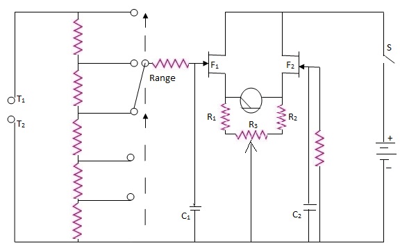 |
| Circuit of an Electronic Voltmeter using FETs |
The micro ammeter is connected across the two source terminals as shown in the figure above.
(b) Initial Adjustments of Electronic Voltmeter Using FET:
The d.c. supply is to be applied. The test terminals are to be shorted. The variable resistor R3, is to be adjusted to get zero indication in the micro ammeter.
(c) Measurement of Electronic Voltmeter Using FET:
The range selector switch is to be kept in the first position (lowest voltage range). A standard voltage is to be applied to get full scale deflection in the meter. This is a design point. The supply voltage for the FETs, the bias on the gates, the parameters of the FETs determine this input voltage required for obtaining the full scale deflection. It is to be ensured by proper design of component values and selection of FETs that the meter gives a full scale deflection for a standard voltage. The dial of the current/null meter can now be calibrated in terms of volts.
Higher voltages can be measured by properly selecting the ranges. The value of the voltage can be obtained by multiplying the reading with the proper multiplication factor for that range. The dial also can be marked with values corresponding to two or more ranges.
Tags:
Multimeters