
Wheatstone Bridge Design and Working:
The schematic diagram of the Wheatstone bridge is shown in Figure. It consists of four resistance arms. A battery is used to supply the bridge. A sensitive ammeter or a galvanometer is used as a null detector. The magnitude of the current flowing through the null detector is dependent on the potential difference between points 'c' and 'd'. The bridge will be balanced if there is no potential difference between the points 'c' and 'd'.\
The balance condition occurs when the voltage across the resistance R1 equals the voltage across the resistance R2 with reference to the positive terminal of the battery. Similarly the bridge balance will occur when the voltage across the resistance arms R1 and R4, are equal. Thus when
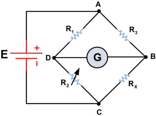 |
| Wheatstone Bridge |
The balance condition occurs when the voltage across the resistance R1 equals the voltage across the resistance R2 with reference to the positive terminal of the battery. Similarly the bridge balance will occur when the voltage across the resistance arms R1 and R4, are equal. Thus when
I1R1 = I2R2 -------------- (1)
When the null indicator indicates ‘0’
I1 = I3 = E/(R1 + R3) ---------------- (2)
I2 = I4 = E/ (R2 + R4) ---------------- (3)
Substituting the values of I1 and I2 in equation (1), and simplifying yields
R1 /(R1 + R3) = R2/(R2 + R4) --------------- (4)
From equation (4), we get
R1R4 = R2R3 --------------- (5)
The above equation is the balance equation of the Wheatstone bridge.
(a) Components of the Wheatstone Bridge:
As has been mentioned above, the bridge consists of four resistance arms as shown in the Figure. Resistors R1 and R2 are named as the ratio arms. The resistance R3 is called the standard arm. There will be no resistance present in the fourth resistance arm. The unknown resistance R4 takes the place of the fourth arm.
Ratio control switch will be provided in the practical Wheatstone bridge. The switch permits switching of the resistance of the ratio arms in decade steps. The resistance of the standard arm will also be provided with a switching arrangement usually in four steps for balance adjustment. Wheatstone bridge can be used to measure resistance from 1 ohm to few mega ohm.
(b) Measurement of Unknown Value of Resistance:
The unknown resistance will be connected to the terminals that form the fourth arm of the bridge. The ratio of the ratio arms may be adjusted to suit easy balance. Using the standard arm switches the bridge will be brought to balance condition where the null indicator indicates '0'. The value of unknown resistance can be estimated from the settings of the standard arm switches. This is because we know from equation 5, that
R1R4 = R2R3
As the unknown resistance takes the place of R4 , the value of the unknown resistance Rx, can be expressed as, Rx = R3(R2/R1)
The value of resistance indicated by this bridge, is dependent on the proper calibration of the null detector, either galvanometer or sensitive current meter.
Tags:
Bridges