
Electromagnetic waves can be transmitted to the load using transmission lines of the open wire type or cables. As the frequency of working increases beyond 300 MHz. it becomes difficult to use transmission lines or cables. The reason is the magnitude of losses in the line and the associated dielectrics used in forming the line or the cable.
12. Waveguide behaves as a high pass filter allowing only those modes which have higher frequencies, than the critical cutoff frequency. So, one can design a waveguide to allow only that mode of interest to propagate.
At frequencies above 3000 MHz we use a metallic tube for the transmission of electromagnetic waves. As a matter of fact the open wire transmission line or the co-axial cable, used as transmission path can be called as a 'waveguide', because the line or the cable guides the electromagnetic wave from the generator to the load.
However this name WAVEGUIDE in Microwave Engineering is used only to specially made hollow metal pipes that carry electromagnetic waves at microwave frequencies. Hence we can say that a WAVEGUIDE is a hollow conducting metallic structure (tubular) used for the transmission of electromagnetic waves. The electromagnetic waves are transmitted by successive reflections from the inner walls of the structure.
Types of Propagation of Electromagnetic Waves at Microwave Frequencies
There are three types of propagation possible for the electromagnetic waves at microwave frequencies. They are:
The transverse electric or TE wave
The transverse magnetic or TM wave
The transverse electromagnetic or TEM wave
The transverse electric waves are the simplest form of electromagnetic wave that can be propagated in a media. It has no component of electric field in the direction of propagation. The waves in which the electric field is wholly transverse are called transverse electric or TE waves.
The transverse magnetic waves have no component of magnetic field in the direction of propagation. The waves in which the magnetic field is wholly transverse are called transverse magnetic or TM waves.
The waves in which both the electric and magnetic field components are transverse to the direction to propagation are called transverse electromagnetic or TEM waves.
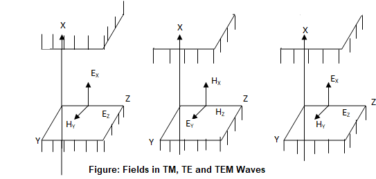
The fields in the TM, TE and TEM waves using vector notation are shown in Figure.
Let the direction of propagation of wave be 'z' direction as shown in Figure. The magnetic field is always transverse to the direction of propagation in TM waves. Therefore = = 0. Hence the electric field has components and y with since no electric field exists in the direction of magnetic field as represented in figure.
In the transverse electric waves x = z = 0 and the electric field is made wholly transverse to the direction of propagation ‘z'. The magnetic field has components Hx; Hz and Hy = 0. This is shown in Figure.
In the TEM wave the magnetic field is wholly along y axis and no field exists in the ‘z’ direction. This is shown in figure.
The following are the equations that represent the TM, TE and TEM waves:
γĤy = (σ + jωƐ) Êx --------------------------- (1)
∂Hy/∂x(σ + jωƐ) Ê ---------------------------(2)
γ Êz + ∂Êz/∂x = jωμĤy -------------------------------(3)
Equations (1) to (3) represent TM wave.
γĤy + ∂Êz/∂x = -(σ + jωƐ) Êy ------------------------------(4)
γ Êy = - jωμĤZ ---------------------------- (5)
∂Êz/∂x = - jωμĤz -------------------------------(6)
Equations (4) to (6) represent TE wave 0
γĤZ= (σ + jωƐ) Êx ---------------------------- (7)
∂Ĥy/∂x = 0 -----------------------------(8)
γ Êy = jωμĤy ----------------------------- (9)
Equations (7) to (9) represent TEM waves.
In these equations 'γ' is the propagation constant is the electric field vector, H is the magnetic field vector m is the permeability s is conductivity, q is the dielectric constant and w is the radiant frequency.
Types of Waveguides - Important Characteristics of Waveguides :
The physical structure of a Waveguides in Microwave Engineering can be anything that is supported by electromagnetic waves. Waveguides can be of rectangular, circular, elliptical, single ridged or double ridged. However the irregular shapes are complicated for analysis. Therefore popularly rectangular and circular wave guides are used. Therefore we classify waveguides into only two principle types.
There are two types of waveguides that are commonly used. They are :
(a) Rectangular waveguides and
(b) Circular waveguides
The important characteristics of waveguides are given below :
1. Waveguides are hollow metal tubes and used for transmission of very high frequencies with as low attenuation as is possible.
2. At ultra high and microwave frequencies, waveguides provide a practical alternative to transmission line for transmission of electrical energy.
3. Skin effect is not experienced in waveguides.
4. Any configuration of electric field and magnetic field that exist inside a waveguide must be a solution of Maxwell equations. Further these fields must satisfy the boundary condition imposed by the walls of the guide.
5. As the walls of a waveguide are perfect conductors, there can be no tangential component of electric field at walls.
6. Many different field configurations can be found inside a waveguide which satisfy the boundary conditions and solutions of Maxwell equations. Each such configuration is termed as a 'mode'.
7. The various possible field configurations or modes that can exist in a waveguide belong to one or the other of the two fundamental types. They are transverse electric or simply TE mode. TE mode is also referred as 'H' mode. The second mode is t transverse magnetic or simply TM mode. It is also referred as 'E' mode. The different modes of each class are represented by double subscripts such as TE10.
8. When travelling along a waveguide have a phase velocitY and will be attenuated.
9. Waves a wave reaches the end of a waveguide it is reflected unless the load impedance is adjusted carefully to absorb the wave.
10. An irregularity in a waveguide produces reflections as is the case with the transmission line.
11. A particular mode will propagate down a waveguide with low attenuation only if the wavelength of the wave is less than the critical cutoff value, determined by the dimensions and geometry of the guide.
12. Waveguide behaves as a high pass filter allowing only those modes which have higher frequencies, than the critical cutoff frequency. So, one can design a waveguide to allow only that mode of interest to propagate.