
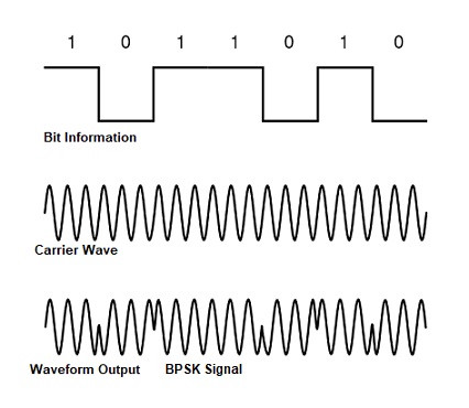
Binary Phase Shift Keying (BPSK) is a form of phase modulation using two different carrier phases to signal 1 and 0. BPSK is the simplest type of PSK. In binary phase shift keying (BPSK), the phase of a stable amplitude carrier signal is toggled amid two values with respect to the two likely signals m1 and m2 equivalent to binary 1 and 0, respectively. Normally, the phases are separated by 1800.
 This system may be represented using a single basis function

The two signals are therefore given by:
S1 (t) = √( 2Eb/Tb) cos (2πfct)
S2 (t) = √( 2Eb/Tb) cos (2πfct +π ) = -√( 2Eb/Tb) cos (2πfct),
where fc is the carrier frequency. The relationship among bit information and waveform signal output and initial phase from modulator is illustrated as Figure.
φ1 (t) = √( 2/Tb) cos (2πfct), 0 ≤ t ≤ Tb
with the two signal vectors amplitude given by
S1 = √Eb
S2 = -√Eb
Where Eb is the signal energy which is also in his case the energy per bit.
A coherent binary PSK system is therefore characterized by having a signal space that is one dimensional with a signal constellation consisting of two message points of equal and opposite amplitude. Such signals with equal energy and a cross correlation coefficient of -1 are called antipodal.
This signal space diagram is shown in Figure. If the symbols are equiprobable then the rule for deciding which symbol was transmitted is to choose the closest message point. The BPSK transmission system is illustrated as Figure.
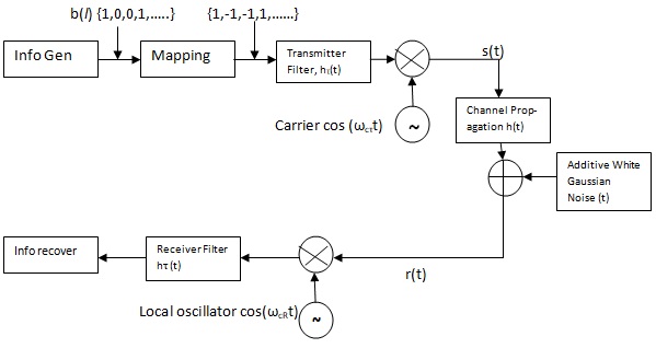 |
| BPSK System Block Diagram |
From the Figure, we can describe the BPSK transmission system as 3 parts:
• Transmitter
• Receiver
• AWGN Channel.
Transmitter Part :
By using the block diagram in Figure above, if we generate, the binary number randomly we will get the information' sequences. Information generated: {b(i)} = 1, 0, 0,…..1.
This bit information sequences will modulate the carrier frequency, and the phase of the carrier frequency will shifted as function of binary information.
The bit information "1" will not shift the carrier phase, and the bit information "0" will shift the carrier phase by 1800 or radians.
Receiver Part :
Basically the receiver part as similar with the transmitter part, but the function is contradictive. After demodulate process by using local signal oscillator and filtering by using LPF, the base band signal will be decided.
If the amplitude of the base band signal is < 0 it's decides that a binary "0" was send and if the amplitude of the baseband signal is ≥ 0, the receiver decides that binary "1" was send by the transmitter.
This description is made by assumption that all of the, process of modulator, Band Pass Filter, demodulator and filtering is work perfectly and inter symbol inter fervencies (ISI) is not happen.
The AWGN Channel :
The signal output from transmitter part is propagated through the channel, which is corrupted by the additive white Gaussian noise, and illustrated in the Figure.
Thus the received signal at the receiver part will have a form :
r(t) = s(t) + n(t); 0 ≥ t ≥T
where n(t) denotes a sample function of the additive white Gaussian noise (AWGN) process with variance value σ2 = No/2 Watt/Hertz. Here we made an assumption that the mean value of the AWGN is 0.
SPECTRUM & BANDWIDTH OF BPSK SYSTEM:
Recalling that our BPSK signal is s(t) = Ac m(t) cos(ωct) , we can use the convolution theorem to calculate its spectrum.
The spectrum of cos(wct) is [δ(f - fc) + 6(f + fc)]/2, so
S(f)= (Ac/2)M(f - fc) + (Ac/2) M(f + fc)
while M ( f ) is called the fourier transform of m(t).
To calculate the specific sequence of logic states is to be known. If the bits are assumed random, then the power spectrum of m(t) is identical to the power spectrum of a single bit. Hence we have
|S(f)|2 = Tb sin c2 [Tb(f – fc)]
This is illustrated in Figure and compared to the MSK spectrum.
 |
| BPSK Spectrum |
The wider main lobe of BPSK as compared to MSK, and the much larger side lobes show that BPSK is not bandwidth efficient as MSK.
The bit rate of BPSK is Rb = Tb. The bandwidth is well approximated by B ≈ 1/ Ts = 1/ Tb.
The spectral efficiency is πBPSK = Rp/B = (1/Tb)/(1/Tb) = 1 bps/Hz
Tags:
Digital Transmission